


ENGLISH
U-CONTROL UMX250 User Manual
5
Channel Messages:
◊
Here, channel-specic control information
is transmitted. An example of a channel message is the note-on
instruction. As soon as a key is played on the keyboard of the
UMX250, the device generates an instruction which contains the
pitch, channel number and velocity. The receiving sound generator
“knows” which tone has to be played.
System Messages:
◊
These messages are not channel-specic but
relate to the entire system to which they are sent. They are divided
into 3 groups: System Exclusive Messages (for operating system
backup, updates, management of memory contents); System Real-
Time Messages (e.g. for remote control of other devices); System
Common Messages (e.g. for the synchronization of several devices).
Control Messages:
◊
Also known as Control Changes or
Controllers, abbreviated as “CC… (Control Change)”. There are
128 controllers in total, which are numbered from 0 to 127.
Controllers are always channel-specic.
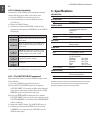
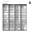
Please refer to Table 6.1 to nd out which type of controller •
you are currently working with.
MIDI data are only control data and contain no audible •
audio information! The data transmission takes place over
16 channels.
What settings do I have to make? Where? How?
Basically, which control element generates which controller
must be set on the UMX250, and how incoming controller com-
mands should be interpreted must be set on the receiving device.
Regarding controller assignment, there are two possible
principles:
You
◊
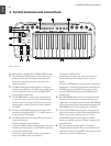
use the preset controller conguration set in the factory (see
Fig. 3.1,
(10)
). In this case, you only need to make the assignments
on the receiving device.
You use your own controller conguration set up in ASSIGN mode.
◊
How to assign controllers to the UMX250 is described in Chapter 4
“OPERATION”.
USB mode and stand-alone 2.2
operation
The UMX250 can be operated as a USB interface or stand-alone
device. The two modes are different with respect to the MIDI
signal ow.
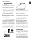
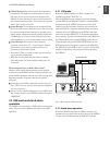
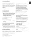
USB mode2.2.1
When the UMX250 is linked via USB to a computer, the
signalow is as shown below (Fig. 2.1).
After the UMX250 has been connected to the host computer,
a virtual MIDI IN and MIDI OUT interface is emulated.MIDI
data generated in the UMX250 are rst sent over the USB
interface to the host computer, where they are received at the
emulated MIDI IN. A sequencer software running on the host
computer receives the MIDI data via the MIDI IN and relays
them to the emulated MIDI OUT—if all sequencer parameters
are set properly. The data are then sent back to the UMX250 via
the USB interfaces on the computer/UMX250, where they are
looped through to the physical MIDI OUT
(14)
. From here, the
MIDI data are sent to the devices connected to the MIDI OUT.
The MIDI OUT connector
(14)
can also be used as a normal MIDI
interface, independently of the sequencer software operating
the UMX250.
Stand-alone operation2.2.2
When the UMX250 is not linked via USB to a computer, it is
automatically set to stand-alone mode. In this case, the UMX250
can only send out MIDI data from its MIDI OUT connector.
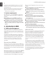
Sound-Module
MIDI
(intern)
IN
OUT
USB
(intern)
Fig. 2.1: Block diagram of MIDI signal ow