


ENGLISH
U-CONTROL UMX250 User Manual
7
The eight buttons B1 – B8 generate switch controllers. Again, these
{9}.
are factory-set functions (see table
(10)
on the device). Like the rotary
controls the buttons can be freely assigned to any controller in
ASSIGN mode.
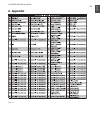
The table shows the controller assignment preset at the factory.
[10].
Keyboard legend: Informs you about the special functions
[11].
performed by individual keys on the keyboard. The individual
elements of the keyboard legend are described in detail in
Chapter 4 “OPERATION”.
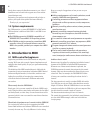
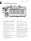
Use this socket to supply the UMX250 with current from an
[12].
external power supply unit (not included).
The USB connector of the UMX250. The connector (type B) on the
[13].
device is connected using the cable supplied to a free slot on the host
computer (where you will nd a type A connector). It is compatible
with the USB 1.1 and USB 2.0 standards.
In addition to the connection to the computer, you can use the MIDI
[14].
OUT to connect additional MIDI devices, so that the UMX250
transforms into a fully-featured, easily accessible MIDI interface for
your host computer.
Use the FOOT SWITCH connector to connect a sustain pedal. This
[15].
port is factory-set and assigned to the MIDI parameter “Foot Pedal”
(CC 64), which represents a switch controller. When the pedal is
pressed (and held) in normal Play mode, it generates a controller
with the value 127. When the pedal is released, the controller falls
back to 0 (typical piano sustain pedal behavior). Apart from that the
pedal assignment is the same as the button assignment, i.e. you can
assign any MIDI controller to it.
The POWER switch is used to switch the unit on and off.
[16].
Please close all programs if you want to switch off the
◊
UMX250 while the computer is running or terminate the
USB connection.
Operation4.
In the following, we will explain the operation of the UMX250
in detail. Please note the differentiation between buttons (see
control elements
(9)
) and keys (control element
(1)
)! Please do
not confuse these!
PLAY mode4.1
After power-up the UMX250 is in PLAY mode. You can start
playing, modify lter sweeps with the rotary controls, determine
program changes intuitively, realize panorama changes, control-
soft synths, and so on.
The FACTORY MEMORY4.1.1
The FACTORY MEMORY is the internal memory storing the
basic settings of the UMX250. The most important feature of the
FACTORY MEMORY is the controller map described in point
(10)
. These settings dene a number of useful parameters and are
automatically loaded when the device is switched on.
Assignments that are modied during a session, will be dis-
carded when the unit is switched off. In order to save the
modied assignments, the UMX250 has been provided with a
USER MEMORY.
The USER MEMORY4.1.2
Settings that are stored in the USER MEMORY, are stored per-
manently in the internal ash ROM and will be retained even
after switching the unit off.
Change to the USER MEMORY by pressing button 6. When you
access the USER MEMORY for the rst time, it stores a copy of
the FACTORY MEMORY settings. As soon as you make changes
to the existing controller map, they are stored automatically
without your intervention.
The following control element assignments including channel
information can be permanently stored in the USER MEMORY:
FOOT SWITCH connector•
OCTAVE SHIFT button•
VOLUME/DATA fader•
PITCH BEND wheel•
MODULATION wheel•
Rotary controls R1 – R8•
Buttons B1 – B8•
OperationOctave shiftLED
press once
Shift one octave
up or down
LED on
press 2nd
time
Shift 2 octaves
up or down
flashing
press 3rd time
Shift 3 octaves
up or down
flashing
press both
buttons
Reset (all octave
shifts are reversed)
LED off
Table 3.1: LED activity depending on the OCTAVE SHIFT status
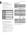
Fig. 3.2: Rear panel connectors