


18 19X32 RACK DIGITAL MIXER Quick Start Guide
X32 RACK DIGITAL MIXER Getting started
(EN) Step 3: Getting
started
Ch01
01:
0:00 - 0:00
A: S16 A: 48K
B: - C: X-USB
: 19
01
home
aux out
analog out
p16 out
card out aes50-a aes50-b
13:45
Inputs 1-8 Inputs 17-24Inputs 9-16
Channel Processing Block Patch
Inputs 25-32 Aux In 1-4
Connected Devices
Local In 1-8
Local In 9-16
[Local In 17-24]
[Local In 25-32]
AES50 A1-8
AES50 A9-16
AES50 A17-24
AES50 A25-32
AES50 A33-40
AES50 A41-48
AES50 B1-8
AES50 B9-16
AES50 B17-24
AES50 A25-32
Local In 1-8
Local In 9-16
[Local In 17-24]
[Local In 25-32]
AES50 A1-8
AES50 A9-16
AES50 A17-24
AES50 A25-32
AES50 A33-40
AES50 A41-48
AES50 B1-8
AES50 B9-16
AES50 B17-24
AES50 A25-32
Local In 1-8
Local In 9-16
[Local In 17-24]
[Local In 25-32]
AES50 A1-8
AES50 A9-16
AES50 A17-24
AES50 A25-32
AES50 A33-40
AES50 A41-48
AES50 B1-8
AES50 B9-16
AES50 B17-24
AES50 A25-32
Local In 1-8
Local In 9-16
[Local In 17-24]
[Local In 25-32]
AES50 A1-8
AES50 A9-16
AES50 A17-24
AES50 A25-32
AES50 A33-40
AES50 A41-48
AES50 B1-8
AES50 B9-16
AES50 B17-24
AES50 A25-32
Aux 1-4
Local 1-4
AES50 A1-4
AES50 B1-4
Card 1-4
AES50 A
AES50 B
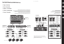
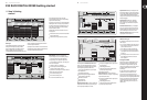
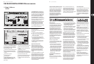
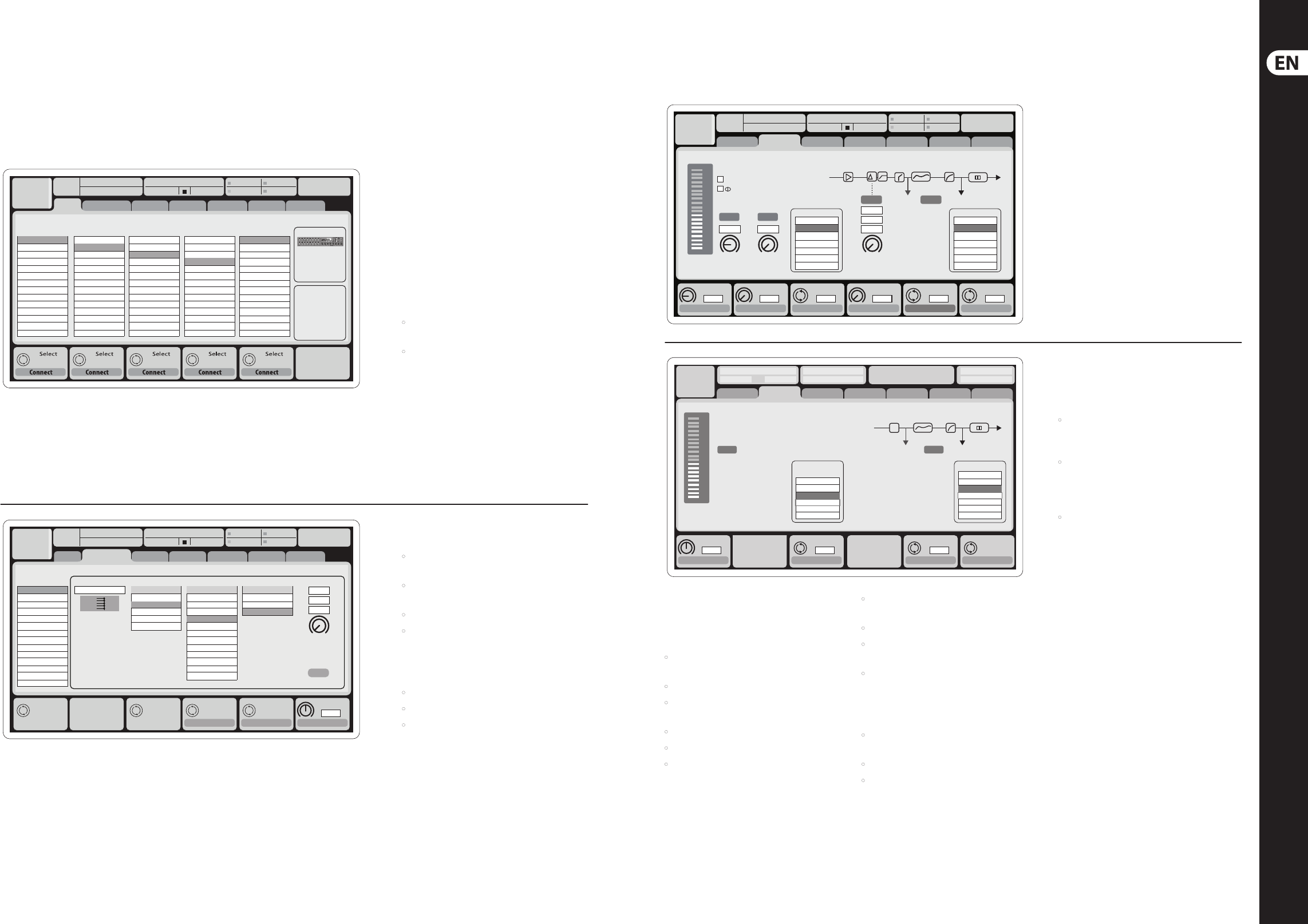
Note: All signal blocks patched to the audio
processing will be connected to the corresponding
input channels automatically.
Local inputs 17-24 and 25-32 are listed with brackets,
indicating that these are not physically available on
this device. Assigning these will obviously carry no
signal, but they can still be used when preparing
shows for a full X32 console.
Cabling for AES50 connections between X32 and
S16 stageboxes:
• Shielded CAT-5e cable, Ethercon terminated cable
ends (recommended)
• Maximum cable length 100 meters (330 feet)
Delay
ms
0.3
Set DelayAssign
ft
m
ms
0.3
0.3
0.10
Delay
Delay
Select Select Select Select
Ch01
01:
01
home aux out
analog out
p16 out
card out aes50-a aes50-b
Analog Output
CategoryCurrent Setting
Edit Output Assignment
Processed Output Signal Tap
0:00 - 0:00
A: S16 A: 48K
B: - C: X-USB
: 37
14:09
Output 01
Output 02
Output 03
Output 04
Output 05
Output 06
Output 07
Output 08
*Output 09
*Output 10
*Output 11
*Output 12
*Output 13
*Output 14
MixBus
OFF
Main (LRC)
Mix Bus
Matrix
Direct Out
Monitor
OFF
Main L
Main R
Main C/M
Main Bus 01
Main Bus 02
Main Bus 03
Main Bus 04
Main Bus 05
Main Bus 06
Main Bus 07
Main Bus 08
Main Bus 09
Pre EQ
Post EQ
Pre Fader
Post Fader
Link Lo Cut
Ch01
01:
01
0:00 - 0:00
A: S16 A: 48K
B: - C: X-USB
: 37
14:11
-6
-12
-18
-24
-30
-36
-42
-48
-54
clip
home gate dyn eq sends main
cong
Gain
Gain
48V
In
Pre PostIns
Delay
dB
+0.00
Link
Lo Cut
Lo Cut
Hz
20
Lo Cut
Input
Select
Source
PRE
Insert
Ins Pos
InsF
Connect
Insert
ms
0.3
Delay
Delay
Delay
dB
+0.0
Hz
2.0
Reverse
t
ft
m
ms
0.3
0.10
0.03
Source
OFF
Input 01
Input 02
Input 03
Input 04
Input 05
Input 06
Insert
OFF
InsFX 1L
InsFX 1R
InsFX 2L
InsFX 2R
InsFX 3L
InsFX 3L
Insert Position
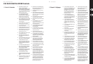
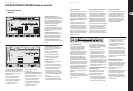
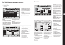
Input Channels 1-16 are pre-congured to use
the local input signals 1-16, but can be patched to
use any other available signal on the audio engine
as well, including mix bus/sub group outputs.
Changesof the Channel Source can be made on the
Preamp Congpage.
Input Channels 17-32 are pre-congured
to AES50 A inputs 1-16, so that connecting an
S16 stage box to port A will automatically feed
thechannels.
Aux Return Channels 1-8 are pre-congured
to use the 6 aux input signals, and the two USB
playback outputs, but can be patched to use any
other available signal of the console as well.
FX Return Channels 1L-4R control the 4 stereo
output signals of side-chain FX1-4.
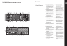
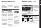
Output Signals can be freely assigned from
anyinternal signal to any of the following outputs:
• 8 analog local XLR outputs (with adjustable
digital delay for time-alignment of speakers)
• 8 virtual outputs (marked with *) for routing over
AES50 or card outputs
• 6 auxiliary sends on ¼" TRS outputs
• 16 channel personal monitoring using the
console’s P-16 Bus output connector
Any and all of the above signals can also be mirrored
in blocks of 8 signals on either one of
• 48x channels on AES50 port A
• 48x channels on AES50 port B
• 32x channels on USB interface card
Inputs
-6
-12
-18
-24
-30
-36
-42
-48
-54
clip
Link
Gain
dB
00.00
Send Pos. Insert Pos. Insert
Link Bus Sends
Insert
Connect
Pre
LeOnde.mp3
29 November 2010 Scene01
13:44:43 MyProj.prj
00.05.00 00.00.00
home gate dyn eq sends main
cong
Bus Conguration Bus Insert Position
Insert
Ins 02
FX 01
FX 02
Ins 01
...
Ins 03
Ins 04
All Channel Sends
Pre Conguration
Inputs
Sub Grou
...
Post Fader
Pre EQ
Pre Fader
Insert PostPre
∑
Channel Sends
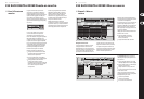
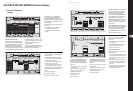
Eects Processing 1-8
The X32 RACK contains eight true-stereo internal
eects engines.
• FX 1-4 can be congured as side chain or insert
eects, while FX 5-8 can only be used in insert
points of channels or buses
• The FX Home screen allows selection of the
FX 1-4 input sources and selecting the eects
type/algorithm for each of the 8 FX slots of the
virtual rack
• The subsequent tabs FX 1-FX 8 of the FX screen
allow editing all parameters of the chosen
eects processor
iPad App for X32 RACK
Many functions of the X32 RACK console can be
remotely controlled by a dedicated iPad app.
Details about the app’s download, setup and
operation are included in a separate user manual
available for download from the X32 RACK
product page.
The app’s User Interface is optimized for the
touchscreen nature of the iPad device and
concentrates on the most important remote
features of the console only. Using the app, you can
perform functions such as adjusting monitor mixes
from the stage while interacting with musicians,
or adjusting the front-of-house mix from the
audience, while hearing the mix exactly as the
audience does.
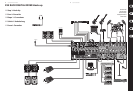
Routing I/O
The X32 RACK console features 16 analog rear-panel
XLR inputs with microphone preamps, as well as
8rear-panel XLR Outputs and 6 TRS Aux Sends and
Returns. In addition, there are two AES50ports,
eachfeaturing 48 input and output channels, andacard
slot for 32channels of input and outputtoand from a
connected computer via USB2.0.
Input Signals can be attached to the console’s internal
audio processing engine in blocks of 8signals from any
one of the aforementioned inputsources.
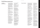
The conguration of Mix Bus Channels 1-16 can
be pre-set (in the Setup/Global page) or can also
be congured on an individual, per-channel basis.
Thebus processing includes (in this order):
• Insert point (swappable between post-EQ and
pre-EQ operation)
• 6-band fully parametric EQ
• Compressor/expander (swappable between
post-EQ and pre-EQ operation)
• Bus sends to 6 matrices
• Main LR panning
• Mono/Center level
Main Bus Channels LR/C are always available and
independent from Mix Buses. The processing steps
for this signal path include (in this order):
• Insert point (swappable between post-EQ and
pre-EQ operation)
• 6-band fully parametric EQ
• Compressor/expander (swappable between
post-EQ and pre-EQ operation)
• Bus sends to 6 matrices
Matrix Channels 1-6 are fed exclusively by
MAINLRC and Mix Bus 1-16 signals. The processing
steps include (in this order):
• Insert point (swappable between post-EQ and
pre-EQ operation)
• 6-band fully parametric EQ
• Compressor/expander (swappable between
post-EQ and pre-EQ operation)