


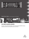

12 13X32 RACK DIGITAL MIXER Quick Start Guide
X32 RACK DIGITAL MIXER Controls
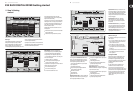
(EN) Step 2: Controls
(1) (3) (4) (5) (11) (13) (17)(6) (10) (16) (21)
(7) (8) (19) (20)(9) (12) (14) (15) (18)
(22)
(2)
(23) (24) (31)
(26)
(25)
(27) (29)(28) (30)
(10)
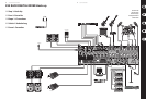
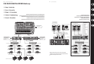
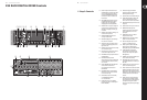
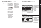
(1) USB button opens the Recorder View on
the MAIN DISPLAY, causing the LED to glow
green. The LED will glow red to indicate
access on the DATA/AUDIO input. An unlit
LED indicates no data access and inactive
Recorder View.
(2) DATA/AUDIO USB input allows connection
of USB ashdrives for rmware updates,
loading/saving scenes and show les,
and playing back or recording WAV les.
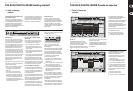
(3) CHANNEL SELECT control cycles through all
channels by turning the knob. By pressing
this knob, you can jump to the next type
of channels.
(4) CHANNEL TYPE LEDs indicate which type of
channel is currently selected.
(5) CHANNEL NUMBER display shows the
currently selected channel.
(6) INPUT METER displays the pre-fader input
level of the selected channel.
(7) SOLO button routes the currently selected
channel to the monitoring paths. The LED
lights when active.
(8) CHANNEL LEVEL control adjusts the currently
selected channel’s output.
(9) MUTE button mutes the currently selected
channel. The LED lights when active.
(10) MAIN MENU buttons open specic menus on
the MAIN DISPLAY.
(11) MAIN DISPLAY shows permanent
information about the mixer’s conguration
as well as information about the currently
selected menu.
(12) DISPLAY ENCODER knobs allow adjustment
and on/o selection of the menu
items indicated at the bottom of the
MAIN DISPLAY.
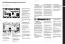
(13) MAIN METER indicates the Main Mono or
SOLO level in the left meter and the Main
Stereo level on the right.
(14) PAGE SELECT buttons curse horizontally
in the MAIN DISPLAY and make
Yes / No conrmations.
(15) LAYER SELECT buttons access dierent
parameter layers that can be edited by the
DISPLAY ENCODERS.
(16) TALK button engages the Talkback
microphone. Routing is dened in the
Monitoring Preferences page.
(17) TALK LEVEL knob sets the Talkback mic gain.
(18) CLEAR SOLO button lights to indicate that
one of the channels has been Soloed.
Press to deactivate all active solo functions.
(19) MAIN LR LEVEL knob adjusts the main stereo
output bus.
(20) ON/OFF button turns the power on and o.
(21) MONITOR LEVEL knob adjusts the
headphone and monitor output volume.
Connect headphones to the ¼" front
panel input.
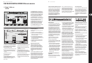
(22) TALKBACK input connects a talkback
microphone via XLR cable.
(23) MONITOR outputs send audio to monitor
speakers via ¼" balanced cables.
(24) AUX IN and OUT jacks send and receive
signals via ¼" and RCA connectors.
(25) XLR OUT jacks send audio via XLR cable.
Output signals are congured on the
Routing/Aux Out page of the MAIN DISPLAY.
(26) X-USB card provides 32 channels of
input and output via USB cable to and
from any connected personal computer
DAWapplication.
(27) ETHERNET connector allows full OSC-based
remote control of the X32 RACK.
(28) MIDI IN/OUT allows the unit to send and
receive MIDI commands via standard 5-pin
DIN cables.
(29) ULTRANET connector sends 16 channels of
audio to a P16 monitoring system.
(30) AES50 A and B connectors allow 96 channels
of bidirectional audio for connection to S16
digital snakes or other X32 family products.
Shielded CAT-5e cable should always be used
for AES50 connections between X32 and
S16 units.
(31) XLR IN jacks receive inputs via XLR cable.
These inputs feature 16 MIDAS-designed
mic/line preamps with 72 dB of gain range.
Each input has an adjacent red LED to
indicate when 48 V phantom power supply
is engaged.