


— 9 —
CIRCUIT DESCRIPTION
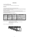
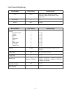
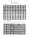
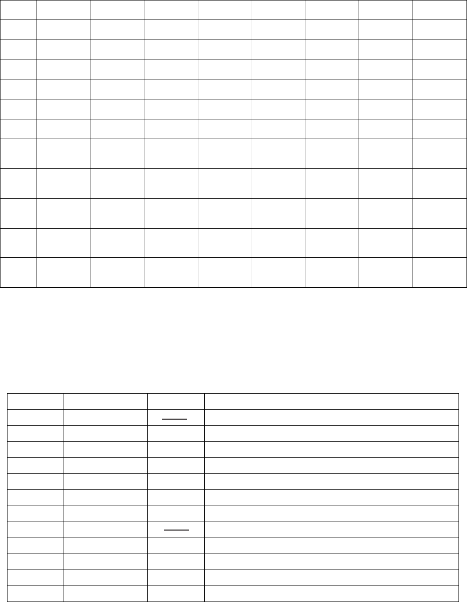
Key Matrix
KI0 KI1 KI2 KI3 KI4 KI5 KI6 KI7
KO0 F3 F#3 G3 G#3 A3 A#3 B3 C4
KO1 C#4 D4 D#4 E4 F4 F#4 G4 G#4
KO2 A4 A#4 B4 C5 C#5 D5 D#5 E5
KO3 F5 F#5 G5 G#5 A5 A#5 B5 C6
KO4 Pad 0 Pad 1 Pad 2 Pad 3 Pad 4
KO5 Enter Pad 5 Pad 6 Pad 7 Pad 8 Pad 9
KO6
Volume
Up
Volume
Down
Bend
Sense
MIDI CH. Control
KO7
Pitch
Bend -
Pitch
Bend +
KO8
Modula-
tion
KO9
Velocity
ff
Velocity
f
Velocity
mf
Velocity
mp
Velocity
p
Velocity
pp
KO10 Internal MIDI Out
Octave
Shift C6
Octave
Shift C5
Octave
Shift C4
Octave
Shift C3
Octave
Shift C2
Octave
Shift C1
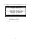
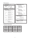
Pin No. Terminal In/ Out Function
1, 2 TEST1, TEST2 Not used. Connected to ground.
3 RESET In Power ON reset input. On: +6V Off: 0V
4 AVDD In +5 V sorce for the built-in DAC
5 OUT Out Sound waveform output
6 AGND In Ground (0 V) source for the built-in DAC
7 GND In Ground (0 V) source
8 COSI In 21.725 MHz clock pulse input
9 COSO Not used.
10 VDD In +5 V source
11 ~ 18 KI0 ~ KI7 In Input terminal from keys and switches
19 KO11 Out MIDI signal output
20 ~ 30 KO10 ~ KO0 Out Key and switch scan signal output
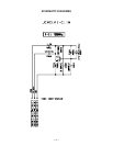
CPU (LSI101: MSM6387-A23)
Containing a MIDI controller, the CPU outputs MIDI messages in accordance with the pressed keys and
buttons.
The following table shows the pin functions of LSI101.