


— 10 —
CRDB
CWRB
CKI
CCSB
CD0
CD7
CA0 ~ CA2
First contact
Second contact
KC0
KC7
FI0
FI9
SI0
SI9
Key input signal
Key scan signal
~
~
Data bus
Address bus
Key Controller
LSI16
HG52E35P
Keyboard
FI
SI
KC
RDAB
WRAB
CLKA
HGB
RESET
RESB
LSI17
HG52E35P
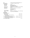
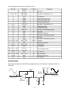
Pin No. Terminal In/Out Function
1 SEL In Mode selection terminal. Connected to ground.
2 D.GND In Ground (0 V) source for the internal digit circuit
3 NC — Not used.
4 DVDD In +5 V source for the internal digital circuit
5 A.GND In Ground (0 V) source for the right channel
6 R.OUT Out Right channel sound waveform output
7, 8 A.VDD In +5 V source for the internal analog circuit
9 R.REF In Right channel reference voltage terminal
10 L.REF In Left channel reference voltage terminal
11 L.OUT Out Left channel sound waveform output
12 A.GND In Ground (0 V) source for the left channel
13 LRCK In Word clock input
14 LRSEL In Not used. Connected to ground.
15 SI In Sound data input
16 CLK In Bit clock input
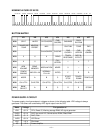
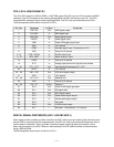
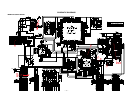
DAC (IC11: UPD6376GS)
The DAC receives 16-bit serial data output from the DSP. The data contains digital sound data of the
melody, chord, bass, and percussion for the right and left channels. The DAC converts the data into
analog waveforms by each channel and output them separately.
The following table shows the pin functions of IC11.
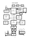
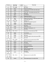
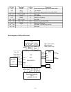
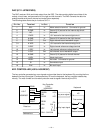
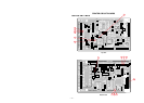
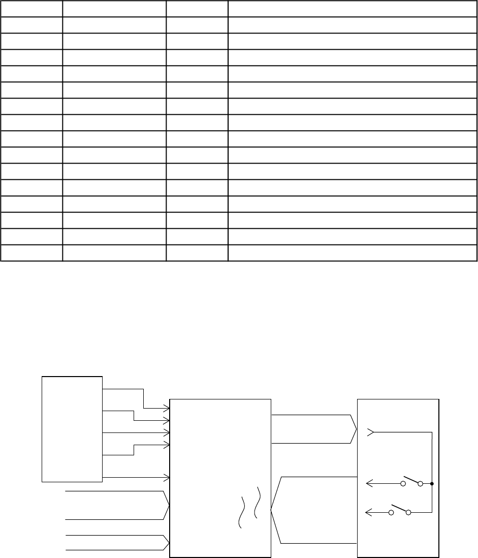
KEY CONTROLLER (LSI16: HG52E35P)
The key controller generates key scan signals and provides them to the keyboard. By counting the time
between first-key input signal FI and second-key SI from the keyboard, the key controller detects key
velocity. The note number and its velocity data are read at regular intervals by the CPU.