


— 12 —
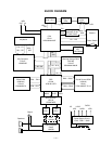
VDD
Battery set
RESET
CPU
LSI14
HD6433294A19F
Reset IC
IC13
RH5VL36AA
Working Storage RAM
LSI15
TC55257DFL-70L
DSP
LSI11
HG51B155FD-1
Key Controller
LSI16
HG52E35P
DVDD
DVDD
DVDD
VDD
VDD
-RESET
POWER
From power switch
KO Signal Generator
LSI17
UPD65611GB-019-3BA
-NMI
To power supply circuit
APO
P42
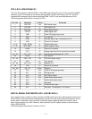
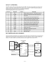
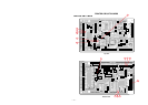
POWER AMPLIFIER (IC201: LA4620)
The power amplifier is a two-channel amplifier with standby switch.
6
16 2 10 11 13
12
Pre-drive
Amp.
Input
Amp.
Power
Amp.
+
–
Pre-drive
Amp.
Input
Amp.
Power
Amp.
+
–
9
7
3
5
+
–
Input
Amp.
Pre-drive
Amp.
Power
Amp.
+
–
Input
Amp.
Pre-drive
Amp.
Power
Amp.
4
19
20
21
22
23
1
18
17
15
14
8
RL Short
Protector
RL Short
Protector
Terminal
Protection
Circuit
Pop Noise
Prevention
Circuit
Ripple
Filter
IN11+
IN11–
IN12–
IN21+
IN21–
IN22–
NC DC MUTE ADJ
Boot11
OUT11
PoGND1
OUT12
Boot12
VCC1
Boot21
OUT21
PoGND2
OUT22
Boot22
VCC2
PriGND
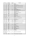
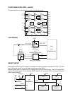
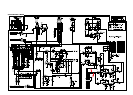
RESET CIRCUIT
When batteries are set or an AC adapter is connected, the reset IC provides a low pulse to the CPU. The CPU
then initializes its internal circuit and clears the working storage RAM.
When the power switch is pressed, the CPU receives a low pulse of POWER signal. The CPU provides APO
signal to the power supply circuit and raises RESET signal to +5 V to reset the DSP, the key controller and
the KO signal generator.
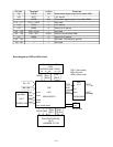
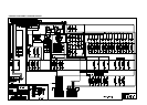
IC17
UPD65611GB-019-3BA
LG
CPU
LSI14
HD6433294A19F
LVDD
P40
P41
KO0 ~ KO3, KO5
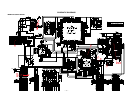
IC301
BA612
LED Driver
Q15 ~ Q18
LED Driver
LD0 ~ LD7
La ~ Lg, Lp
KO Signal Generator
LED DRIVING