


4
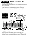
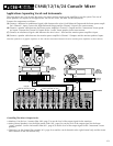
The Input Channels:
1
2
3
4
5
6
7
8
11
12
13
14
9
10
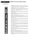
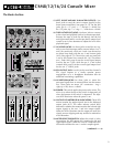
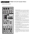
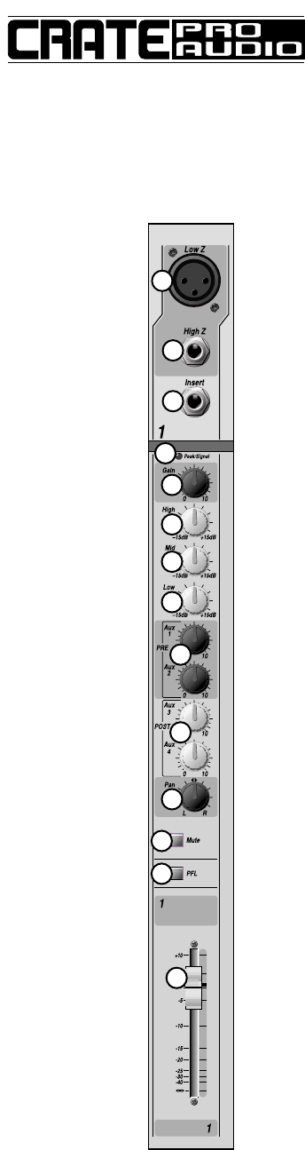
1. LOW Z INPUT: The signal output from a low impedance microphone or a low
impedance line level signal (such as a line out signal from an instrument ampli-
fier) may be connected here by means of a shielded cable terminated with a
male XLR plug. Pin 2 = “+,” pin 3 = “–,” and pin 1 = shield.
2. HIGH Z INPUT: The signal output from a high impedance microphone or a line
level signal (such as an instrument, rhythm machine, tape deck, etc.) may be
connected here by means of a shielded cable terminated with a male 1/4” plug.
Tip = “+,” ring = “–,” and sleeve = shield.
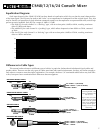
3. INSERT: A signal processor may be connected here by means of a shielded
stereo signal cable or shielded “Y” cord. (See page 8.) Ring = send, tip = return,
and sleeve = ground.
4. PEAK/SIGNAL LED: This LED will illuminate green when a signal is present at
the High or Low Z inputs. When the signal nears clipping, the LED will illumi-
nate red. (See Gain control, #5.)
5. GAIN: Use this control to set the input signal level for the channel. Adjust this
control so the peak LED (#4) flashes on strong signal peaks.
6. HIGH: Use this control to adjust the high frequency level for the channel. This
control allows for 15dB of cut or boost at 10kHz. Typical equalization diagrams
are shown on page 7.
7. MID: Use this control to adjust the midrange frequency level for the channel.
This control allows for 15dB of cut or boost at 2kHz. Typical equalization dia-
grams are shown on page 7.
8. LOW: Use this control to adjust the low frequency level for the channel. This
control allows for 15dB of cut or boost at 100Hz. Typical equalization diagrams
are shown on page 7.
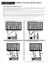
9. AUX 1, AUX 2: Use these controls to set the channel’s output signal level at the
aux 1 and aux 2 send jacks (#17, page 5). These are pre-EQ, pre-fader, and are
typically used as monitor sends. Examples of some typical connection methods
are shown on pages 8–13.
10.AUX 3, AUX 4: Use these controls to set the channel’s output signal level at the
aux 3 and aux 4 send jacks (#17, page 5). These are post-EQ, post-fader, and
are typically used as effects loop sends. Examples of some typical connection
methods are shown on pages 8–13.
11. PAN: Use these controls to set the amount of the channel’s output signal sent to
the left and right master faders (#30, page 6) and the left and right balanced out-
put jacks (#15, page 5).
12.MUTE: This switch, when depressed, mutes the channel’s output signal sent to the
left, right and mix master faders (#30, 31, page 6).
13.PFL: This switch, when depressed, sends the channel’s post-EQ, pre-fader signal
to the headphones jack (#28, page 6) and the PFL output jack (#18, page 5).
14.FADER: Use this control to set the channel‘s signal level output sent to the left,
right and mix master faders (#31, 32, page 6) and the aux 3 and aux 4 send jacks
(#17, page 5).
CSM8/12/16/24 Console Mixer