


5
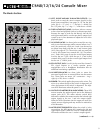
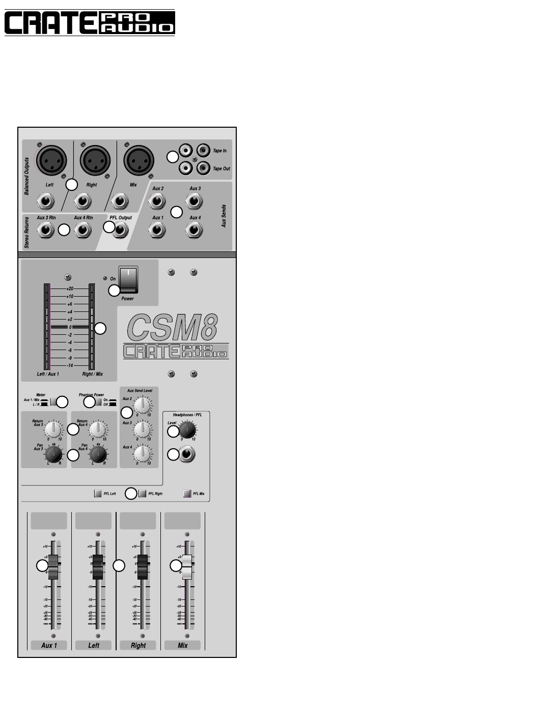
The Master Section:
15
16
18
17
20
22
25
26
24
27
28
29
30 31 32
23
21
19
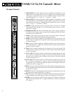
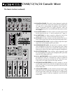
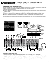
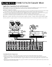
15. LEFT, RIGHT AND MIX BALANCED OUTPUTS: Use
these jacks to send the mixer’s output signal(s) to the
house power amplifier(s) (see pages 9–13). For the XLR
jacks, pin 2 = “+,” pin 3 = “–,” and pin 1 = shield. For
the 1/4” jacks, tip = “+,” ring = “–,” and sleeve = shield.
16. TAPE IN/TAPE OUT JACKS: Use these jacks to connect
to the record and playback jacks of a cassette tape deck.
Because the tape in jacks are fed directly into the left
and right master faders, use the tape deck’s output level
control or an in-line attenuator to adjust the level of the
playback signal.
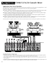
17. AUX SEND JACKS: Use these jacks to send the aux sig-
nals to your monitor amps and/or external effects. Aux 1
and 2 are sends only, while aux 3 and 4 can be used as
an effects loop along with the aux 3 and 4 return jacks
(#19). (See pages 8–13). The mix for each aux send jack
is set by the channel aux controls (#9, 10). The master
aux 1 fader (#30, page 6) sets the overall signal output
level for the aux 1 jack, while the aux 2, 3 and 4 send
controls (#24, page 6) set the overall signal output level
for the aux 2, 3 and 4 jacks.
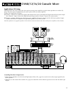
18. PFL OUTPUT JACK: Use this jack to send the channel’s
PFL signal outputs to a studio monitor power
amp/speaker or to a headphone distribution box for
additional monitoring capabilities.
19. AUX RETURN JACKS: Use these jacks to return the
processed signal from an external effect into the master
mix. These jacks are stereo 1/4” connectors – ring =
right, tip = left, sleeve = shield.
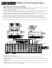
20. POWER: This switch applies the power to the mixer. The
mixer is on when the top of the switch is depressed, off
when the bottom of the switch is depressed. The adja-
cent LED illuminates when the power is on.
21: OUTPUT LED METERS/PEAK INDICATORS: These LED
meters monitor the output signals sent to the balanced
output jacks (#15). The meter selector switch (#22)
determines whether the meters monitor the left and right
output signals or the aux 1 and mix output signals.
When the LEDs illuminate into the upper red areas, the
signals are near clipping and may need to be reduced to
avoid distortion.
22: METER SELECTOR SWITCH: When the switch is in the
out position, the LED meters (#21) monitor the left and
right output signals. When the switch is depressed, the
LED meters monitor the aux 1 and mix output signals.
CSM8/12/16/24 Console Mixer
(continued...–––––
>
)