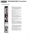
The Master Section (con’t):
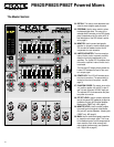
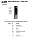
31. LIMITER/LED METER: The mixer employs inter-
nal limiter circuits to prevent overdrive distortion
from being reproduced by the amplifiers. The
Limiter LEDs illuminate when either of the main
amplifiers’ internal limiter circuits are activated.
The two sets of five-step LED displays directly
below the Limiter LEDs indicate the levels of the
left and right main’s output signal.
32. DSP SEND LEVEL: Use this control to adjust the
level of signal at the DSP Line Out jack (#40) and
to the internal DSP processor.
33. PEAK: This LED illuminates when the DSP signal
level nears clipping. During normal operation, this
LED will flash on strong signal peaks. If the LED
remains illuminated, reduce the DSP Send Level
control (#32).
34. HEADPHONES LEVEL: Use this control to adjust
the level of the signal at the (Headphones) jack
(#42).
35. EFF RETURN LEVEL: Use this control to adjust
the level of the internal DSP applied to the Tape
Out jacks (#45), the Main Out Left / Right jacks
(#46), and the Speakers - Left / Right jacks (#48,
page 9).
36. AUX IN LEVEL: Use this control to adjust the level
of the signal applied to the Main outputs from the
Aux In - Left / Right jacks (#43).
37. TAPE IN LEVEL: Use this control to adjust the
level of the signal from the Tape In - Left / Right
jacks (#44) applied to the Main outputs.
38. MAIN LEVEL: Use this control to adjust the overall
level of the signal at the Main Out Left / Right jacks
(#46) and the Speakers - Left / Right jacks (#48,
page 9).
39. BRIDGE/STEREO: Use this switch to determine
whether the main power amplifiers are bridged
together for a single output signal (at the up posi-
tion) or work separately for a stereo output signal
(at the down position).
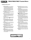
40. DSP LINE OUT: Use this jack to send an output
signal to an external effects device. Connect this
jack to the effect’s input jack by means of a shield-
ed signal cable.
41. DSP FOOTSWITCH: Use this jack to connect a
footswitch to the mixer for remote on/off control of
the internal DSP. The footswitch must be a normal-
ly open / momentarily closed type (such as the
Crate model #FSIU). The wiring for the footswitch
is shown at the bottom of this page.
42. (HEADPHONES): Use this jack to connect a
pair of stereo headphones to monitor the main out-
put signals. The level of the signal is adjusted by
the Headphones Level control (#34).
43. AUX IN - LEFT / RIGHT: Use these jacks to con-
nect an external effects device’s output signal or to
feed another mixer’s signal into the mixer. These
jacks are post-input channel, pre-eq and pre-power
amp, and the signal levels are adjusted by the Aux
In Level control (#36).
44. TAPE IN - LEFT / RIGHT: Use these jacks to con-
nect the output signal from a tape deck or CD play-
er to the mixer. The signal level is adjusted by the
Tape In Level control (#37).
45. TAPE OUT - LEFT / RIGHT: Use these jacks to
connect the output of the mixer to a tape recorder.
These jacks are pre-eq, pre-master, and their sig-
nal level is adjusted by the channel Level controls
(#8, #19).
46. MAIN OUT - LEFT / RIGHT: Use these jacks to
connect the mixer’s pre-amplified output signal to
an external power amplifier, recording console, or
to the Aux In jack of another Crate powered mixer.
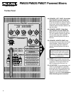
48. MONITOR OUT: Use this jack to send a pre-ampli-
fied signal to an auxiliary monitor amplifier (or pow-
ered monitor).
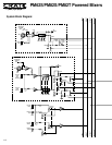
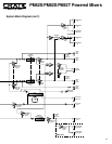
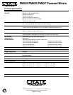
Wiring for the DSP footswitch (#41):
7
PM62S/PM82S/PM82T Powered Mixers


