


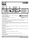
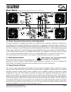

Mode Selection.
The three-position, recessed Mode Select switch (located on the rear panel) configures the amplifier for
either Stereo, Parallel or Bridged Mono Mode. Amplifiers are factory-configured for Stereo Mode.
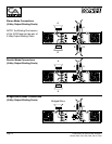
Stereo Mode.
In Stereo Mode, both channels operate independently, with their input attenuators controlling their respec-
tive levels. Signal at Channel A’s input produces output at Channel A’s output, while signal at Channel B’s
input produces output at Channel B’s output. Recommended minimum nominal load impedance for stereo
operation is 2 ohms per channel. Either the 1/4" (TRS) inputs or the XLR inputs may be used.
Parallel Mode.
When set to Parallel Mode, a signal applied to Channel A’s input will be amplified and appear at outputs for
both Channels A & B. Either the 1/4" (TRS) input or the XLR input on Channel A may be used.
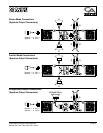
Bridged Mono Mode.
Bridged Mono Mode straps both amplifier channels together to make a very powerful, single-channel
monaural amplifier. One channel “pushes” and the other “pulls” equally, doubling the power over that of
either channel alone. Signal is applied to the Channel A input only. Both attenuators are used to control sig-
nal level; in addition, both must be adjusted to the same setting. Either the 1/4" (TRS) or XLR input may be
used.
NOTE: The channel B input connectors (XLR and/or TRS) may be used to “loop thru” the channel A signal
when in parallel or bridged mono mode.
Use extreme caution when operating the amplifier in Bridged Mono Mode. Never ground either side of the
speaker cable when the amplifier is in Bridged Mono Mode; both sides are “hot.” If an output patch panel
is used, all connections must be isolated from each other and from the panel. The recommended minimum
nominal load impedance in the Bridged Mono Mode is 4 ohms, which is the equivalent to driving both
channels separately at 2 ohms. Driving bridged loads of less than the recommended minimums will activate
the IGM circuitry, resulting in a loss of power, and may also lead to a thermal protect condition.
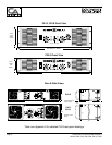
See figures on pages 12 & 13 showing output connection information.
Crest Audio CA Series Power Amplifiers Page 11
Models CA2, CA4, CA6, CA9, CA12, CA18
Connecting amplifier outputs to oscilloscopes or other test equipment while the
amplifier is in bridged mode may damage both the amplifier and test equipment!