


Crest Audio CA Series Power Amplifiers Appendix E
Models CA2, CA4, CA6, CA9, CA12, CA18
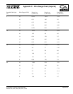
Appendix E
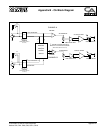
CA18 Power Amplifier - Special Functions
XLR Pin +
GAIN
Ø
dBu
40x
20x
A
B
+
AB
A
A
A
B
A
A
B
B
A
B
B
A
+
+
+
Designed & manufactured in the USA by:
Crest Audio Inc.
100 Eisenhower Dr.
Paramus, New Jersey 07652 USA
2 3
1
3
2
XLR Pin +
GAIN
Ø
dBu
40x
20x
A
B
+
2 3
1
3
2
AB
A
A
A
B
A
A
B
B
Designed & manufactured in the USA by:
Crest Audio Inc.
100 Eisenhower Dr.
Paramus, New Jersey 07652 USA
B
A
NL4FC
B
A
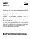
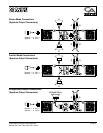
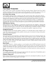
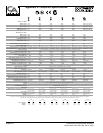
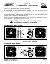
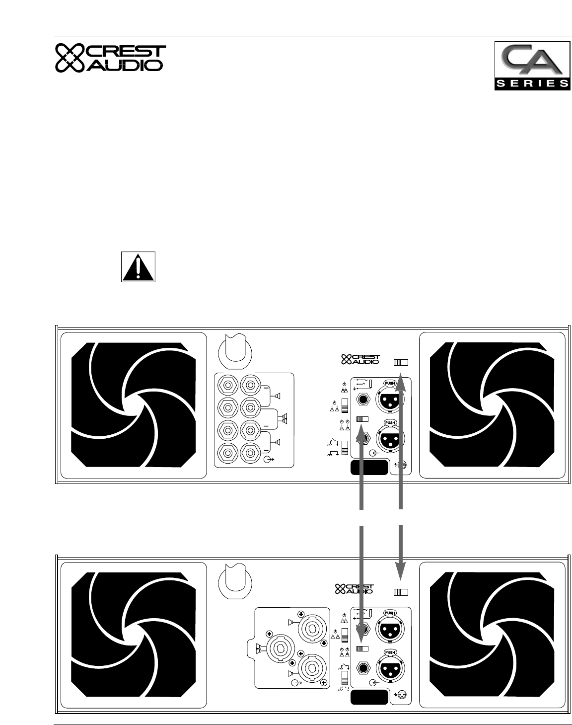
The CA18 rear panel features external switches for the following:
XLR Pin+ Switch: This switch configures XLR input connection polarity. Either pin 2 or pin 3 may be
selected as the “hot” (+) pin. Amplifiers are shipped pin 2 “hot” (+) from the factory.
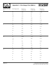
Gain Switch: This switch permits the amplifier to be configured for the standard input sensitivity (.775V
for rated power @ 8Ω), or for optional voltage gains of X40 or X20. Refer to the specifications for input
sensitivity values at optional voltage gains of X40 and X20.
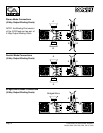
NOTE: on the 5-way Output Binding Post version of the CA18, two pairs of 5-way binding posts are provid-
ed for each channel, so that paralleling of speakers is possible.
XLR Pin (+) Switch
Gain Switch
CA18 Binding Post Version - Rear View
CA18 Speakon Version - Rear View
ALWAYS power down the amplifier before changing settings
with either the XLR Pin+ switch or the Gain switch!