


Power Base Series Power Amplifiers
Page 11
3.3.1
ODEP
Crown invented
ODEP
to keep the amplifier working
under demanding conditions and to increase output
efficiency. To do this, Crown established a rigorous pro-
gram to measure each transistor’s
safe operating area
(SOA). Intelligent circuitry was then designed to simu-
late the instantaneous conditions of the output transis-
tors. Its name describes what it does: Output Device
Emulation Protection, or
ODEP
. In simple terms,
ODEP
compares transistor conditions to their known SOA. If
more power will be asked of them than they can deliver
under the existing conditions,
ODEP
limits the drive
until conditions fall within the SOA. Limiting is propor-
tional and kept to an absolute minimum—only what is
required to prevent output transistor damage. Under
normal conditions, no limiting is required and
ODEP
is
transparent to the audio signal.
ODEP
makes possible a quantum leap in output effi-
ciency and reliability—with
ODEP
, the show goes on.
3.3.2 Ultrasonic and Radio Frequency Protection
An amplifier’s slew rate only needs to be large enough
to deliver the maximum voltage at the highest required
frequency. Higher slew rates actually allow undesirable
ultrasonic and radio frequencies to be reproduced. By
design,
Power Base
amplifiers have a controlled slew
rate to limit the highest frequencies that they reproduce.
Limiting occurs well above 20 kHz so there is no au-
dible effect on performance. This approach protects
the amplifier from radio frequencies and can even pro-
tect some sensitive loads (including some tweeters).
3.3.3 Drive Protection
The drive protection system temporarily removes output
drive to protect the amplifier and its loads. Drive protec-
tion can be activated in two situations. First, if dangerous
subsonic frequencies or direct current (DC) is detected
in the amplifier’s output, the unit will activate its DC/low-
frequency protection circuitry which puts the amplifier in
drive protection mode. This protects the loads and pre-
vents oscillations. The unit resumes normal operation as
soon as the amplifier no longer detects dangerous out-
put. Although it is extremely unlikely that you will ever
activate the amplifier’s DC/low frequency protection
system, improper source materials like subsonic square
waves or input overloads that excessively clip the input
signal can activate this system.
The amplifier’s fault protection system will put the am-
plifier in drive protection mode in rare situations where
heavy common-mode current is detected in the output.
3 Operation
3.1 Precautions
Although your amplifier is protected from external faults,
the following safety precautions are recommended:
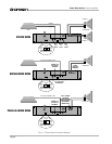
1. There are important differences among the Stereo,
Bridge-Mono and Parallel-Mono operating modes.
Please refer to Sections 2 for additional information.
2. WARNING: Do not change the position of the
stereo/mono switch unless the amplifier is first
turned off.
3. CAUTION: In Parallel-Mono mode, a jumper is
used to connect the red binding post outputs.
Be sure to remove this jumper for Bridge-Mono
or Stereo mode, or high distortion and excessive
heating will occur. Also, make sure the stereo/
mono switch is set to the proper position.
4. Use care when making connections, selecting sig-
nal sources and controlling the output level. The
load you save may be your own!
5. Do not short the ground lead of an output cable to
the input signal ground. This will form a ground loop
and may cause oscillations.
6. Operate the amplifier from AC mains of not more
than 10% variation above or below the selected line
voltage and only at the specified line frequency.
7. Never connect the output to a power supply out-
put, battery or power main. Such connections
may result in electrical shock.
8. Tampering with the circuitry by unqualified person-
nel or making unauthorized circuit changes may be
hazardous and invalidates all agency listings.
Remember: Crown is not liable for any damage that re-
sults from overdriving other system components.
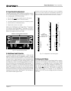
3.2 Power Indicator
When lit, the amber power indicator (to the left of the
power switch) shows that the amplifier has been turned
on. It is driven only by the low-voltage power supply
and does not indicate the status of the high-voltage
supplies.
3.3 Protection Systems
Power Base
amplifiers have extensive protection sys-
tems, including
ODEP
, ultrasonic/RF protection, drive
protection, transformer thermal protection and fuses or
circuit breakers that protect the power supplies.