


Power Base Series Power Amplifiers
Page 9
2 Installation
Always remove power from the unit and turn the level
controls off (fully counterclockwise) when making or
breaking connections. This reduces the chance of
blasts that can cause loudspeaker damage.
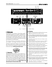
The guidelines below are provided to help you quickly
get your amplifier installed and ready to go. Be sure to
follow the instructions in Sections 2.1 and 2.2 for the
selected mode of operation. Additional information on
input sensitivity, load protection and required AC
mains is provided in Sections 2.3, 2.4 and 2.5.
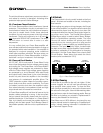
1. Install the amplifier in a standard 19 inch (48.3 cm) rack
or place it on a stable surface. The mounting dimensions
are 19 inches (48.3 cm) wide, 3.5 inches (8.9 cm) tall
and 16 inches (40.6 cm) deep behind the mounting sur-
face. IMPORTANT! Allow for adequate ventilation.
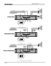
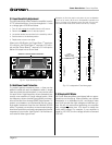
2.1 Stereo
1. Turn down the level controls (fully counterclockwise) and
turn off the amplifier.
2. Set the back panel stereo/mono switch to Stereo.
3. If present, remove the Parallel-Mono jumper.
4. Connect the input and output cables as shown in the first
example in Figure 2.1.
5. Turn on the amplifier and adjust the level for each chan-
nel using the back panel level controls.
CAUTION: Never parallel the two outputs by di-
rectly tying them together, and never parallel them
with the output of another amplifier.
2.2 Mono
Your amplifier’s mono modes provide double the
power of Stereo mode in a single channel. In Bridge-
Mono mode, the outputs are wired in series for twice
the output voltage. In Parallel-Mono mode, the outputs
are paralleled for twice the current capacity.
Bridge-Mono mode is provided for loads with an im-
pedance greater than 4 ohms. Parallel-Mono mode
should be used with loads of 4 ohms or less.
B R I D G E - M O N O
1. Turn down the level controls (fully counterclockwise) and
turn off the amplifier.
2. Set the back panel stereo/mono switch to Bridge-Mono.
3. If present, remove the Parallel-Mono jumper.
4. Connect the input and output cables as shown in the sec-
ond example in Figure 2.1. Only use the channel 1 input.
5. Make sure the load is balanced (neither side shorted to
ground) and do not use the black (–) binding posts.
6. Turn on the amplifier and adjust the level. Only use the
channel 1 level control.
P A R A L L E L - M O N O
1. Turn down the level controls (fully counterclockwise) and
turn off the amplifier.
2. Set the back panel stereo/mono switch to Parallel-Mono.
3. Install a solid, 14-gauge (2 mm
2
) or heavier jumper wire
across the two red (+) binding post outputs.
4. Connect the input and output cables as shown in the third
example in Figure 2.1. Only use the channel 1 input.
5. Turn on the amplifier and adjust the level. Only use the
channel 1 level control.
CAUTION: With Parallel-Mono wiring, do not switch
to Stereo or Bridge-Mono mode until the output
jumper wire is removed.
AIR
FLOW
AIR FLOW
AMPLIFIER
(TOP VIEW)
RACK
CABINET
16 in
40.6 cm
2 in
MIN.
17 in
43.2 cm
AIR
FLOW
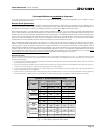
IMPORTANT: Be sure the back of
the amplifier is supported.
–
+
3
1
2
GND
FROM
PREAMPLIFIER
INPUT
BALANCED
+
–
SHIELD
FROM
PREAMPLIFIER
INPUT
UNBALANCED
+
SHIELD
+
3
1
2
SHIELD
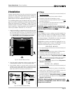
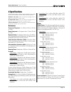
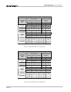
Fig. 2.3 Power Base Input Wiring
2. Use high-quality loudspeaker cables to connect the load
to the amplifier’s outputs. Do not use shielded cable.
3. Use shielded cables to connect audio sources to the
amplifier inputs. Either balanced or unbalanced wiring
can be used as shown below. (XLR connectors are avail-
able with the MT-XLR accessory. See Section 5.)
Fig. 2.2 Do NOT Block Air Flow