


Power Base Series Power Amplifiers
Page 12
The unit should never output heavy common-mode cur-
rent unless its circuitry is damaged. Activating drive
protection helps prevent further damage.
3.3.4 Transformer Thermal Protection
All
Power Base
amplifiers have transformer thermal
protection. This protection circuitry is activated in un-
usual situations where the unit’s transformer tempera-
ture rises to unsafe levels. Under these abnormal
conditions, the unit removes power to the high-voltage
transformer. The fan will continue to run in all units ex-
cept those with 220/240 VAC transformers. The ampli-
fier will return to normal after it cools to a safe
temperature.
It is very unlikely that your
Power Base
amplifier will
ever activate transformer thermal protection as long as
it is operated within rated conditions. Your amplifier is
designed to continue operating under conditions
where other amplifiers would fail. But even when you
exceed the limits of a
Power Base
amplifier, it still pro-
tects itself—and your investment—from damage.
3.3.5 Fuses and Circuit Breakers
All 120 VAC, 60 Hz units and all
Power Base-3
units
have a fuse that protects the low-voltage power supply
and cooling fan. The
Power Base-1
and
Power Base-2
high-voltage power supplies are protected by fuses,
while the
Power Base-3
high-voltage power supplies
are protected by a circuit breaker. With rated loads
and output levels, these fuses (or the circuit breaker)
should only shut down the amplifier in the incredibly
rare instance of a catastrophic amplifier failure. The
ODEP
protection system keeps the amplifier opera-
tional under most other severe conditions. The fuses
(or breaker) can also shut down the amplifier in situa-
tions where extremely low-impedance loads and high
output levels result in excessive current draw.
A
Power Base
amplifier will not blow its fuses or trip its
breaker unless something is wrong. In the rare event
that an internal fuse blows, please refer the unit to a
qualified technician. If the breaker in a
Power Base-3
trips, try to identify and correct the problem before re-
setting it with the back panel Circuit Breaker Reset. If
the problem persists, refer the unit to a qualified techni-
cian.
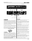
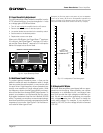
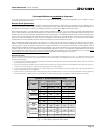
3.4 Controls
The Power switch is th only control located on the front
panel. All others are located on the rear, including the
level controls.
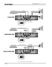
When making any setup or wiring changes, don’t forget
to turn off the amplifier, turn down the level controls and
disconnect the power cord. Be sure to turn down (full
counterclockwise) the channel 2 level control when us-
ing either mono mode. The Parallell Mono/Stereo/
Bridge Mono switch is used to select Stereo, Bridge-
Mono or Parallel-Mono operating modes. The Input
Ground Lift switch isolates the phone jack input
grounds from the chassis ground to help prevent
ground loops. It does not affect any installed input ac-
cessories. The Input Sensitivity Switch, located inside
the back cover plate, sets the amplifier’s input sensitiv-
ity (refer to subsection 2.3 for information on changing
this switch). And the
Power Base-3
has a back panel
Circuit Breaker Reset button that resets the circuit
breaker (refer to subsection 3.3.5).
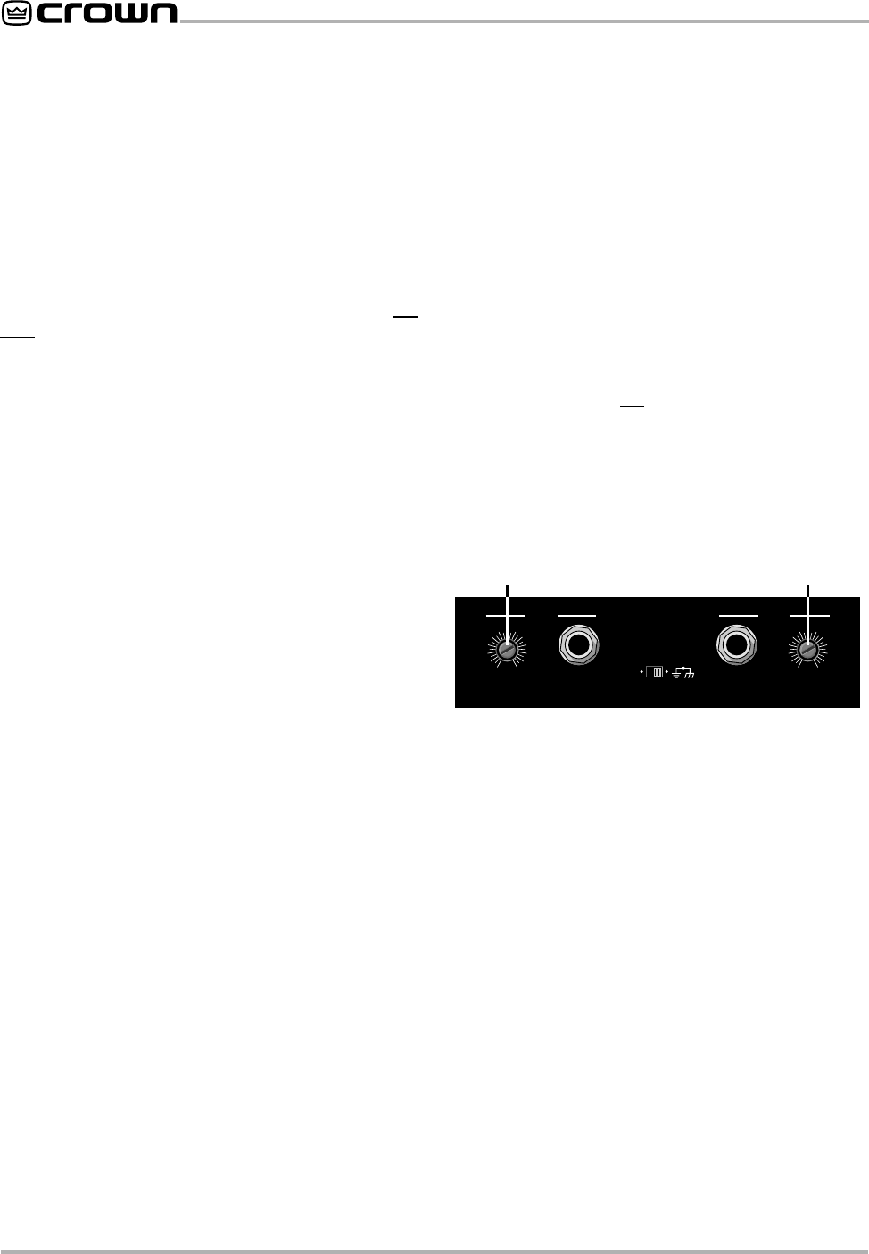
CH-2
INPUT GROUND LIFT
(AFFECTS PHONE INPUTS ONLY.)
(MONO)
INPUT
GAIN
CH-1
INPUT
GAIN
LIFT
0
1
2
3
4
5
6
7
8
9
10
11
12
0
1
2
3
4
5
6
7
8
9
10
11
12
CHANNEL 2
LEVEL CONTROL
CHANNEL 1
LEVEL CONTROL
3.5 Filter Cleaning
A dust filter is provided on the unit’s air intake. If it be-
comes clogged, the unit will cool less efficiently and
may produce lower output levels. To clean the filter,
use a phillips screwdriver to remove the three screws
the secure the front grille. Use mild dishwashing deter-
gent and warm water for best cleaning results. Be sure
the filter is dry before you reinstall it. Replacement fil-
ters may be ordered from the factory.
Dust filters are not 100% efficient—long term this may
require internal heat-sink cleaning by a qualified tech-
nician. Internal cleaning information is available from
our Technical Support Group.
Fig. 3.1 Back Panel Level Controls