


7
ENGLISH
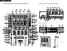
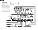
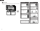
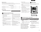
(2) Rear panel
$0 LINE2, 4, 6, 7, 8 input jacks
• These stereo pairs of unbalanced RCA jacks are
inputs for any line level device.
$1 PHONO1, 2, 3 / LINE1, 3, 5 input
jacks
• These stereo pairs of unbalanced RCA jacks are
inputs for a PHONO (RIAA) stage for magnetic
(MM) cartridges or a LINE stage suitable for any
device, such as a CD player.
$2 PHONO1, 2, 3 / LINE1, 3, 5 switches
• These switches change the input from PHONO
to a LINE level inputs.
• These switches set a LINE level inputs when
turntable is not connected.
$3 Phono ground screw (GND)
• This screws provide a place to connect the
ground wire from a turntable.
This terminal is exclusively for a turntable
grounding and not a safety earth ground.
$4 AUX MIC input jack
• Accepts an balanced microphone with 1/4” TRS
mono jacks.
• Pin layout: Tip=Hot Ring=Cold Sleeve=GND
$5 MAIN MIC input connector
• Neutrik combo jack.
• Accepts either a balanced microphone with an
XLR connector or a balanced microphone with
1/4” TRS mono jacks.
• Pin layout:
XLR: 1. GND 2. Hot 3. Cold
1/4” TRS: Tip=Hot Ring=Cold Sleeve=GND
$6 Maintenance connector
NOTE:
This connector can be used only for firmware
updating. Do not connect device, or may cause
damage.
$7 LINE2, 4, 6, 8 FADER output jacks
• Connect these jacks to the FADER input jacks of
DN-S3000, DN-S5000, DN-D4000 and etc. using
the 3.5 mm stereo mini cord.
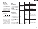
$8 SEND / RETURN jacks
• These 1/4” TS mono jacks allow external
processing of the program signal.
• When connect monaural type effect processor,
use Lch input and output.
$9 DIGITAL OUT (COAXIAL) jack
• This RCA jack provides a digital output data. The
signal is unaffected by the MASTER LEVEL
control.
• We recommend using a 75 Ω/ohm RCA cord for
best digital transfer. (available from any
audio/video retailer)
%0 REC OUT jacks
• This stereo pair of RCA jacks provide a line level
output. The signal is unaffected by the MASTER
LEVEL control.
%1 BOOTH OUT jacks
• This stereo pair of RCA jacks provide a
unbalanced line level output with independent
top panel BOOTH LEVEL control.
%2 MASTER OUT (UNBALANCED)
jacks
• This stereo pair of RCA jacks provide a
unbalanced line level output.
• Connect these jacks to the unbalanced analog
input jacks on an amplifier or console.
%3 LEVEL ATT
(Master out level attenuator)
• Use this to attenuate the MASTER output level.
(–
∞
~ 0 dB)
• Reference is 0 dB.
%4 MASTER OUT (BALANCED)
connectors
• These XLR type connectors provide a balanced
line level output.
• Connect these connectors to the balanced
analog input connectors on an amplifier or
console.
• Pin layout: 1. GND 2. Hot 3. Cold
• Applicable connector:
Cannon XLR-3-31 or equivalent.
NOTE:
Do not short-circuit the hot or cold pin with the
GND pin.
%5 MASTER MONO OUT ON/OFF
switch
• When this switch is on, mixed L and R signal is
outputted from the MASTER OUT (Both
BALANCED and UNBALANCED).
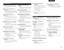
(3) Display
%6 Crossfader A assign indicators
• This indicator shows channels of assigned
channel to Crossfader A side.
%7 Preset mode indicators
%8 Sampler mode indicators
SAMP.:
• The Sampler sound is recorded.
LOOP:
• Playing Sampler in Loop mode.
REV.:
• Reverse Sampler playback.
%9 Character display
• This displays various operational information,
etc..
• [ 1 ] : CH-1 indicator
[ 2 ] : CH-2 indicator
[ 3 ] : CH-3 indicator
[ 4 ] : CH-4 indicator
The number of assigned input source is
displayed on the character display under these
indicator.
^0 Effect assign indicators
• Selected Effector source is indicated here.
^1 Crossfader B assign indicators
• This indicator shows channels of assigned
channel to Crossfader B side.
^2 Effector BPM display
• This display indicates the BPM of the assigned
source.
^3 BPM mode indicators
AUTO:
• This indicator is lit, when the BPM mode is
AUTO BPM.
• This indicator is flashed, when the AUTO BPM
is locked.
MANUAL:
• This indicator is lit, when the BPM mode is
manual BPM input. You can input desired BPM
by MODE PARAMETER knob.
^4 Cue button indicators
• Channels of CUE selected are indicated.
^5 Cue BPM display (Auto count)
• This display indicates the BPM of the selected
channel.
NOTE:
BPM will not be displayed, if 2 or more channels
are selected.