


MS3000 OWNERS MANUAL
page 3
MS3000 SERIES OWNERS MANUAL
MS3000 UHF Diversity Wireless System
Features
Well-designed companding and audio circuitry
deliver hard-wired sound quality
Excellent 104 dB signal-to-noise ratio
Metal chassis ½-rack space receiver with TNC
antenna connectors
Metering for audio level, rf and diversity channel
Externally-adjustable squelch control
Balanced 3-pin XLR-type and unbalanced ¼-inch
audio outputs
Choice of transmitters including rugged bodypack
with TA4F connector for lavalier and headset micro-
phones. Professional handheld transmitters with
choice of Electro-Voice N/D767 dynamic or BK-1
condenser transducers.
DESCRIPTION
The Electro-Voice MS3000 is a professional quality
UHF diversity wireless system that operates within
the frequency range of 690 to 725 MHz (TV chan-
nels 50 55) on single custom-tuned frequencies.
MS3000 Systems combine the MR3000 receiver
with a choice of handheld and bodypack transmit-
ters that allow multiple ways to achieve wireless
freedom. The wide range of frequencies permit use
of multiple systems simultaneously (the exact num-
ber is dependent on local conditions). The specially
designed compander circuitry provides wide dy-
namic range with clean, accurate transient re-
sponse. MR3000 receivers have ½-rack space
metal chassis for ruggedness and reliability. A
host of accessories are available for operational
and installation flexibility.
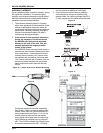
SECURE-PHASE
tm
DIVERSITY
The MR3000 receiver utilizes patented Secure-
Phase
tm
diversity circuitry that ensures the stron-
gest, cleanest signal possible. Unlike other diversity
schemes that switch antennas or signal, Secure-
Phase
tm
utilizes the signal from both antennas at all
times to increase signal strength, minimize dropouts
and lower the potential for interference.
If the signal from the transmitter changes phase or
polarity (a common cause of dropouts), the circuit
adjusts the phase angle between the two antennas
receiving circuits to prevent cancellation. The two
diversity lights on the front panel indicate the status
of this circuit.
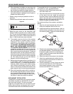
ANTENNAS
The MR3000s ½-rack space receiver has specially
tuned quarter-wave antennas with TNC-type an-
tenna connectors. These connectors are electrically
and mechanically superior to the commonly used
BNC connectors and are located on the rear panel
of the MR3000. TNC connectors are widely used on
cellular communications equipment and are readily
available.
Two antennas are supplied with the unit for normal use
and optional accessory kits can be used to rack mount
or remote-mount the antennas. Other accessories
such as multi-couplers, ½-wave antennas and log
periodic directional antennas are also available to
meet specific installation and use requirements.
HANDHELD TRANSMITTER
Choice of Electro-Voice N/D767 (MSHD) N/DYM
dynamic or Electro-Voice BK-1 condenser (MSHC)
transducers.
Special soft-touch finish and ergonomically
designed handle makes holding comfortable
and secure.
Separate LEDs for power on and battery status
for easy monitoring of operational modes.
Separate power and audio mute switches for
operational flexibility.
Wide-range gain control allows approximately 40
dB of adjustment.
Up to 10 hours of operation on a 9-volt alkaline
battery.
BODYPACK TRANSMITTER
UHF bodypack with TA4F connector allows the
user the freedom of microphone selection with
easy interchangeability. Available microphones
include the Electro-Voice ULM20 cardioid con-
denser lavalier microphone and the HM2 headset
microphone. The TA4F connector allows connec-
tion of any dynamic or condenser microphone
that can be biased with 5 volts DC phantom.
Separate on/off and toggle mute switches for
operational flexibility
LED battery condition indicator gives quick
indication of battery strength
Up to 10 hours of operation on a 9-volt alkaline
battery
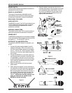
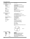
MR3000 FRONT PANEL FEATURES DISPLAYS
The MR3000 has a number of front panel indicators
to make setup and operation easier.
1. A five-segment LED meter shows audio level
and is useful for setting the transmitters gain
control.
2. A five-segment LED RF meter shows the strength
of the incoming signal from the transmitter
3. Two LEDs indicate the action of the Secure-
Phase
tm
diversity circuitry.