


MS3000 OWNERS MANUAL
page 4
POWER SWITCH
The front-panel power switch allows the receiver to
be switched on and off easily.
SQUELCH ADJUSTMENT
The range of the externally adjustable squelch
control allows you the choice of maximizing range
or lowering the potential for external interference.
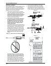
REAR PANEL FEATURES
AUDIO OUTPUTS
The MR3000 has both 3-pin XLR-type balanced and
¼-inch unbalanced phone jack output connectors.
The line level output is adjustable with a small
screwdriver (included).
ANTENNA CONNECTORS
The antenna inputs utilize TNC connectors that pro-
vide solid mechanical and electrical connections.
POWER INPUT
The MR3000 will operate from the supplied ac adapter
or any other battery, filtered supply or power pack that
can deliver 12 15 volts AC/DC, 300 mA.
SYSTEM SET-UP AND OPERATION
To prepare the MS3000 System for operation, you
should:
1. Connect the power supply adapter to an AC
outlet that will supply 105 to 125 volts AC, 60
Hz. Other power supply adapters are available
for 210 240 volt, 50 60 Hz operation. Make
sure that you have the correct power supply for
your locality.
2. Connect the MR3000 to your audio system us-
ing the appropriate connector on the rear panel.
It is preferable to use the 3-pin XLR connector
since its balanced circuitry minimizes the poten-
tial for electrical interference and can be used
with long cable runs.
3. Switch on the receiver with the front-panel
power switch.
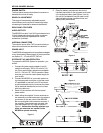
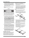
4. Attach either the supplied ¼-wave antennas or
two externally mounted antennas to the antenna
connectors on the rear panel of the MR3000.
Be sure and tighten the connectors securely. If
the supplied ¼-wave antennas are used, they
must be oriented at a 90
o
angle as shown in
Figure 1. Unlike other diversity wireless sys-
tems, two antennas are needed for the
MS3000 to operate correctly.
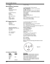
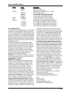
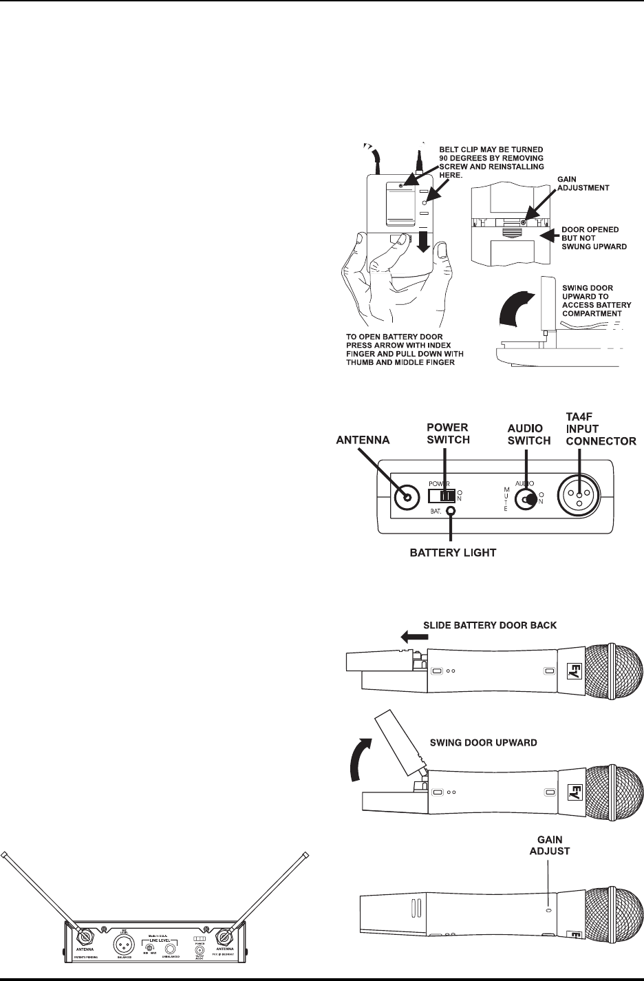
5. Open the battery compartment door on the
handheld transmitter or the bodypack and install
a 9-volt alkaline battery (see Figures 3 and 4).
8.4 volt Ni-Cad batteries may be used but will
yield noticeably shorter operational time and
slightly lower performance.
Figure 1
Figure 2
Figure 3
Figure 4