


MS3000 OWNERS MANUAL
page 5
6. When the battery is installed, you may plug in the
microphone to the bodypack or simply switch on
the handheld transmitter and begin operation.
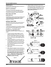
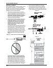
7. When the system is first operated, the gain of the
transmitter should be adjusted to the vocalist or
speaker who will be using it.
Speak or sing as loudly as possible into the mi-
crophone.
Observe the audio level meter on the receiver.
Adjust the gain control on the transmitter (see
Figures 2 and 4) to prevent over or under-modula-
tion. The gain should be adjusted so that the signal
peaks are no more than +0 dB and that there is at
least 10 dB of audio level meter indication.
8. The squelch control on the front of the receiver
may be adjusted to increase range or reduce
interference. If the squelch control is being ad-
justed, it should be adjusted with the transmitter
off. CAUTIONDECREASING SQUELCH WILL
MAKE THE SYSTEM MORE SUSCEPTIBLE
TO OUTSIDE INTERFERENCE! Use the small
screwdriver supplied with the unit and turn the
squelch control clockwise to reduce interference
from noise and spurious radio signals. To best set
the squelch control, turn the control counter-clock-
wise until you hear noise and interference and then
turn it back clockwise until the noise is squelched
off. This setting will give you the best balance
between noise and reduced range.
9. Before using the system before an audience, it is
a good idea to walk the expected use area to
check for dropouts. To minimize the potential for
dropouts, please observe good antenna place-
ment. When the transmitter is turned on, the RF
meter on the receiver should be illuminated in the
green range to verify it is receiving a strong signal.
10. When the transmitter power switch is turned on,
the red battery light will flash one time if the bat-
tery is good and has adequate strength. If the
red light does not flash or stays on continuously,
the battery is weak and should be replaced.
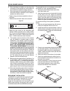
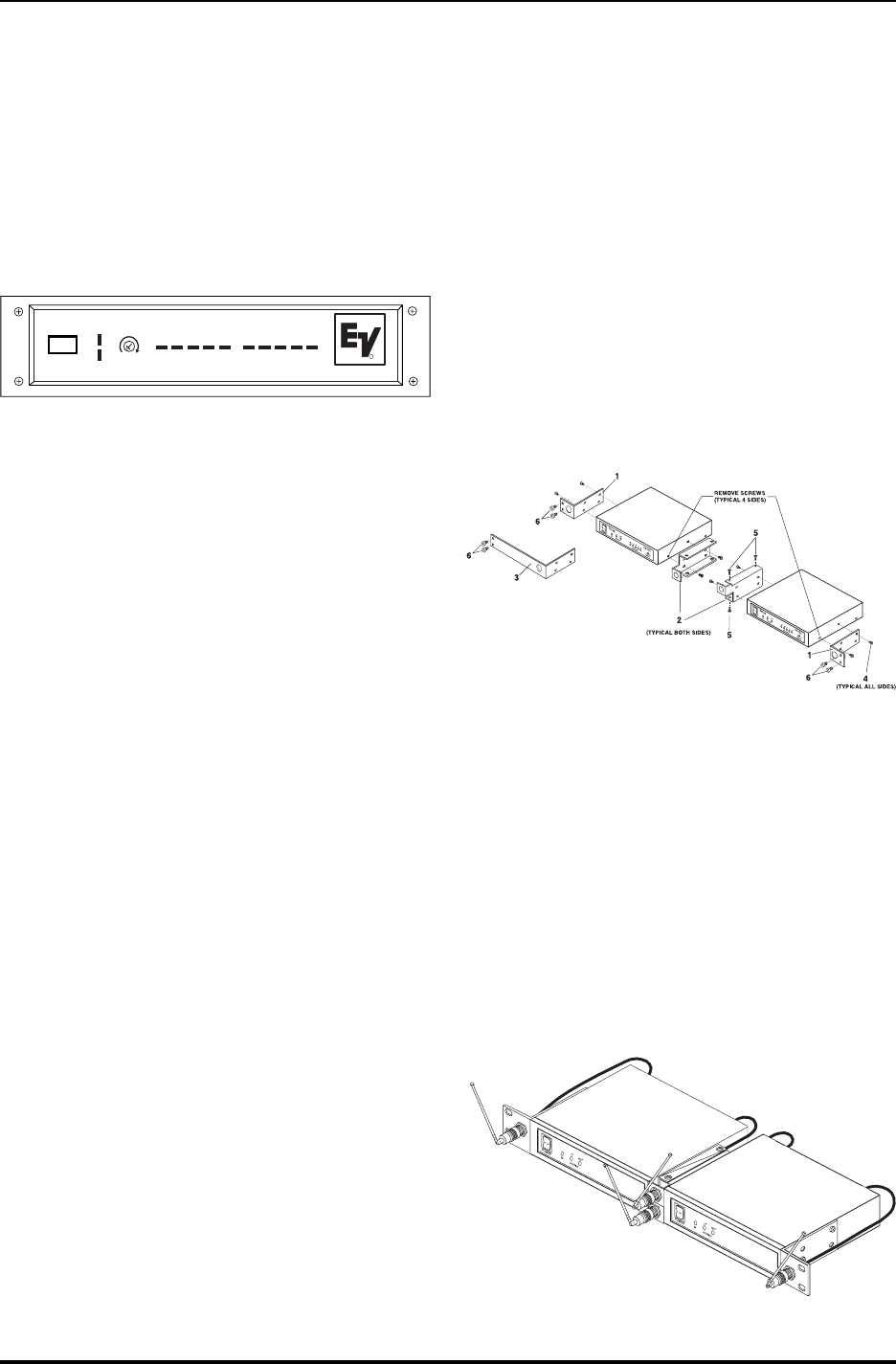
RACK-MOUNT INSTALLATION
The MR3000 is supplied with rack mounts for single
and double mounting in a standard EIA 19 equip-
ment rack (see Figure 6). For rack mounting a
single unit, a long and short ear are used. For dual
side-by-side mounting, use the short ears and the
mid sized brackets from two MR3000s as shown.
To assemble the rack mount adapters to the unit(s)
and install into a rack, proceed as follows:
1. Remove the front Phillips head screws from
each side of each unit.
2. Align the correct rack ear or bracket with the holes
on the side of the unit. Install the previously
removed screws. Insert an additional screw (pro-
vided in the parts pack) into the remaining hole.
Repeat this step for the opposite side of the unit.
Be sure to tighten all screws securely.
For double mounting of two systems, proceed as
follows:
1. Align the mid-sized brackets (item #2) with the
holes on the adjacent sides of each unit.
2. Install the previously removed screws. Insert an
additional screw (provided in the parts pack) into
the remaining holes. Tighten all screws securely.
3. Place the two assemblies side-by-side with the
mid brackets together. (The left bracket should
fit above the right so that the countersinks are
visible). Install 4 flat-head screws (item #5) and
tighten them securely.
4. Attach the antenna connectors to the brackets.
5. Attach the supplied extension cables from the
rack connectors to the antenna connections on
the back of the receiver.
4. Place the assembly in to the 19-inch rack enclo-
sure and insert 4 #10-32 x 3/8 Phillips pan
head screws (supplied) in each corner of the
rack ears and secure to the enclosure.
Figure 6
Figure 7
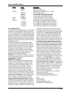
Figure 5
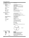
DIVERSITY
MR3000
SQUELCH
RF LEVEL
POWER
AUDIO LEVEL:dB
1
2
R
1
2 3 4 5 -20 -10 -5
0
+
3