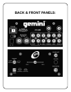
3. On the rear panel are 2 stereo
LINE
(5,6)
inputs and
2 stereo
PHONO
(7,8)
inputs. The phono inputs will accept
only turntables with a magnetic cartridge.
GROUND
SCREWS (9)
for you to ground your turntables are located
on the rear panel. The stereo line inputs will accept any line
level input such as a CD player, cassette player, etc.
4. Headphones can be plugged into the front panel
mounted
PHONES (10)
jack.
Connect
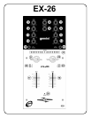
1. POWER ON: Once you have made all the equipment
connections to your mixer, press the
POWER (1)
switch.
2. CHANNEL 1: The
GAIN
(11),
HIGH
(12),
MID
(13),
and
LOW
(14)
controls allow you to fully adjust the volume and
EQ of the sound source. The Channel 1
REVERSE
SWITCH
(15)
allows you to reverse the direction of the
Channel 1 slide fader.
(17)
The Channel 1
SLIDE FADER
17)
controls the input level of this channel.
3. CHANNEL 2: The
GAIN
(11),
HIGH
(12),
MID
(13),
and
LOW
(14)
controls allow you to fully adjust the volume and
EQ of the sound source. The Channel 2
REVERSE
SWITCH
(16)
allows you to reverse the direction of the
Channel 2 slide fader.
(18 )
The Channel 2
SLIDE FADER
18 )
controls the input level of this channel.
4. EQ CONTROLS: There is Low, Mid and High
equalization for each channel with an extremely wide range
of adjustment.
5. INPUT ASSIGN SWITCHES: You can adjust the position
of the
INPUT ASSIGN SWITCHES
(21, 22)
to move left to
right, up and down, or
at a 45 degree angle.
Make these adjustments with the power
OFF
.
1) Remove the channel slide knobs, crossfader knobs and
the 4 screws from the sides of the lower faceplate. Then
remove the lower faceplate.
2) Remove the 2 screws in the corners of the assign switch
plate. Rotate the switch plate to the desired position, and
replace the screws and tighten down.
3) To position the switch at a 45-degree angle, you need to
reposition the switch on the assign switch plate. First,
remove the 2 screws in the corners of the assign switch
plate. Then, lift the switch plate up and remove the 2
smaller screws next to the switch. Rotate the switch plate to
the right until the 45-degree holes align with the switch
holes, replace the screws and tighten down. Replace the
switch plate and tighten down.
NOTE: Keep track of where you position the input
assign switches.
6. CHANNEL SLIDE CURVE SWITCHES: Use the 3
position
CHANNEL SLIDE CURVE SWITCHES (23,24)
to
adjust the kind of curve the channel slides have. Move the
selected channel slide curve switch to the 6 (top) position to
make the increase in level gradual and even. Move the
channel slide curve switch to the 20 (center) position to
make the increase in level less gradual as you move
channel slide up. Move the channel slide curve switch to
the 30 (bottom) position to make the increase in level even
less gradual, especially at the top of the slide.
7. CROSSFADER SECTION: The
CROSSFADER (25)
allows the mixing of one source into another. The left side
of the
CROSSFADER (25)
is CHANNEL 1 and the right
side is CHANNEL 2. The
CROSSFADER CURVE
CONTROL (26)
allows you to adjust the kind of curve the
crossfader has. Move the
CROSSFADER CURVE
CONTROL (26)
to the right to make the curve steep and
cutting (perfect for scratching). Move the
CROSSFADER
CURVE CONTROL(26)
to the left to make the curve
gradual and gentle. The
CROSSFADER REVERSE
BUTTON (27)
allows you to reverse the crossfader so that
CHANNEL 2 is controlled by the left side of the crossfader
and CHANNEL 1 is controlled by the right side of the
crossfader. When REVERSE is activated the
REVERSE
LED (28)
will light.
NOTE: When the CROSSFADER REVERSE BUTTON is
activated (depressed), only the crossfader reverses.
The Channel Slides, Gain,
and EQ controls do not
reverse.
8. OUTPUT CONTROL SECTION: The level of the
MASTER OUTPUT (2, 3)
is controlled by the
MASTER
CONTROL (20).
The
BALANCE CONTROL KNOB (19)
controls the balance between the output of the left and right
channels.
NOTE: The RECORD OUT (4) has no level control. The
level is set by the channel slides and the gain controls
of the selected channel. The EQ of the channels is set
by the low, mid and high controls of that same channel.
9. CUE SECTION: By connecting a set of headphones to
the
PHONES JACK
(10)
, you can monitor the music
coming out of each channel separately or both channels
together. Move the
CUE FADER (29)
to the left to hear
CHANNEL 1 and to the right to hear CHANNEL 2. Move
the
CUE FADER (29)
to the center to listen to both
channels together. The
PHONES MUTE
BUTTON
(30)
will
instantly mute your cue mix.
10. DISPLAY: The red LED in the center of the display tells
you that the power in your EX-26 Mixer is on.
The multi-colored
LED DISPLAY
(31)
on either side of the
center tells you the output level of your 2 channels
.
Okay, that’s it! NOW you’re ready to grab a couple of great
CD’s or records, crank it up and get the party started!
Pa
e 2