


INTRODUCTION:
Congratulations on purchasing a Gemini MM-03 4U 19",
5 channel, rack mounted club mixer. This state of the
art mixer is backed by a three year warranty, excluding
crossfader and channel slides. The crossfader and chan-
nel slides are backed by a separate 90 day warranty.
Prior to use we suggest that you carefully read all the
instructions.
FEATURES:
- 4U 19" rack mounted club mixer
- 5 stereo Channels
- 8 line, 3 Mic, 2 convertible phono/line, RCA inputs
- 3 band rotary line EQ control per channel with cut feature
- Fully removable, user replaceable Rail Glide crossfader
- Assignable cross fader
- Rotary gain control per channel
- Dual display with bright LED
- Push-button cueing with cue/PGM fader control
- Rotary master, zone, balance & cue volume controls
- Master, zone & record RCA outputs
- Balanced master output
- XLR-1/4" combo Mic input
- 2 band rotary Mic EQ control with cut feature
- Rotary Mic volume control
- Auto Talk-Over feature
- Face plate located 1/4" headphone input
CAUTIONS:
1. All operating instructions should be read before using
this equipment.
2. To reduce the risk of electrical shock, do not open the
unit. Please refer servicing to a qualified service techni-
cian.
3. Do not expose this unit to direct sunlight or to a heat
source such as a radiator or stove.
4. This unit should be cleaned only with a damp cloth.
Avoid solvents or other cleaning detergents.
5. When moving this equipment, it should be placed in its
original carton and packaging. This will reduce the risk of
damage during transit.
6. DO NOT EXPOSE THIS UNIT TO RAIN OR MOIS-
TURE.
7. DO NOT USE ANY SPRAY CLEANER OR LUBRI-
CANT ON ANY CONTROLS OR SWITCHES.
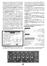
CONNECTIONS:
1. Before plugging the power cord in, make sure that the
VOLTAGE SELECTOR (2) switch is set to the correct
voltage (115 or 230).
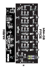
2. Located on the rear panel is the 115/230V PLUG (1)
used to plug in the power cord. Before plugging the power
cord in to the 115/230V PLUG (1) and then into an elec-
trical output, make sure the POWER SWITCH (70) locat-
ed on the face panel is turned OFF.
3. The MM-03 has 4 sets of outputs:
- The BALANCED MASTER (6) output jacks connect-
connect the mixer to main amplifier using standard cables
with 1/4" CONNECTORS. We recommend using balanced
cables if the distance to your amp is 10 feet or more.
- The MASTER (3) output jacks also connect to the main
amplifier with RCA cables.
-The ZONE (5) output jacks allow the connection of an
additional amplifier with RCA cables.
In the USA ~ if you experience problems
with this unit call Gemini Customer Service at: 1
(732) 738-9003. Do not attempt to return this equip-
ment to your dealer.
- The REC (4) output jacks can be used to connect the
mixer to the record input of your recording unit, thus
enabling you to record your mix with RCA cables.
4. Located on the rear panel are 2 Phono(PH)/Line(LN)
convertible RCA inputs (13, 16), and 6 line RCA inputs
(7, 8, 9, 14, 17, 18). The convertible RCA inputs for CH
2 (38) & CH 3 (45) allow PH and LN level equipment to be
connected to the mixer. To adjust the CONVERTER(S)
(12, 15), just flip the switch UP to operate PH 1 or PH 2.
Flip the switch DOWN to operate through LN 2 or LN 4.
The PH INPUTS only accept turntables with a magnetic
cartridge. When using (a) turntable(s), you will need to
ground the RCA cable(s) by screwing in the grounding
fork(s) to the GROUNDING SCREW (11) located in the
back panel of the MM-03 mixer. This is located in between
the CONVERTER SWITCHES (12, 15). The stereo LN
INPUTS only accept line level inputs such as a CD, DAT,
MiniDisc, etc.
NOTE: NOT ATTACHING A GROUND MAY CAUSE A SYSTEM "HUM."
5. Headphones may be plugged into the face-plate located
1/4" HEADPHONE JACK (60).
6. The MIC 1 (20) input (located on the front panel) is a
combination of an XLR and ¼" connector. The MIC 2
(19) and Mic 3 (10) inputs (in the rear panel) accept only
1/4" connectors. The mic inputs accept balanced and
unbalanced microphones.
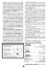
OPERATIONS:
1. Once all of your connections have been in the rear panel,
turn on the mixer by pressing the POWER SWITCH (70).
2. CHANNEL 1: To bring this channel in to program output
(PGM), you must first decide which line will be in use. Use
the LN SWITCH (25) to toggle from LN 1 (18) to MIC 2
(19) on this channel. Slowly raise the CH 1 SLIDE CON-
TROL (31) to a comfortable level, once you've selected
the proper line. You can further modify the sound output of
this channel by adjusting the rotary GAIN (26), HIGH (28),
MID (29), LOW (30) controls located to the left of the CH
1 SLIDE CONTROL (31).
3. Channel 2: To bring this channel in to PGM, you must
first decide which line will be in use. Use the LN SWITCH
(32) to toggle from PH1/LN 2 (16) to LN 3 (17) on this
channel. Slowly raise the CH 2 SLIDE CONTROL (38) to
a comfortable level, once you've selected the proper line.
You can further modify the sound output of this channel by
adjusting the rotary GAIN (33), HIGH (35), MID (36), LOW
(37) controls located to the left of the CH 2 SLIDE CON-
TROL (38).
4. CHANNEL 3: To bring this channel in to PGM, you must
first decide which line will be in use. Use the LN SWITCH
(39) to toggle from PN2/LN4 (13) to LN 5 (14) on this
channel. Slowly raise the CH 3 SLIDE CONTROL (45) to
a comfortable level, once you've selected the proper line.
You can further modify the sound output of this channel by
adjusting the rotary GAIN (40), HIGH (42), MID (43), LOW
(44) controls located to the left of the CH 3 SLIDE CON-
TROL (45).
5. CHANNEL 4: To bring this channel in to PGM, you must
first decide which line will be in use. Use the LN SWITCH
(46) to toggle from LN 6 (9) to MIC 3 (10) on this channel.
Slowly raise the CH 4 SLIDE CONTROL(52) to a comfort-
able level, once you've selected the proper line. You can
further modify the sound output of this channel by adjust-
ing the rotary GAIN (47), HIGH (49), MID (50), LOW (51)
controls located to the left of the CH 4 SLIDE CONTROL
(52).
6. CHANNEL 5: To bring this channel in to PGM, you must
first decide which line will be in use. Use the LN SWITCH
(53) to toggle from LN 7 (8) to LN 8 (7) on this channel.
Slowly raise the CH 5 SLIDE CONTROL (59) to a com-
fortable level, once you've selected the proper line. You
(44)