


can further modify the sound output of this channel by
adjusting the rotary GAIN (54), HIGH (56), MID (57), LOW
(58) controls located to the left of the CH 5 SLIDE CON-
TROL (59).
NOTE: FOR OPTIMAL PERFORMANCE, BEGIN PROGRAM MIX WITH
ROTARY GAIN (26, 33, 40, 47, 54) CONTROLS SET TO ZERO
(ROTATE IT COUNTERCLOCKWISE TO THE LEFT POSITION).
MAKE ALL ADJUSTMENTS IN SOUND OUTPUT WITH THE USE OF
YOUR CHANNEL SLIDE CONTROLS (31, 45, 59, 38, 52), ZONE (66),
BALANCED MASTER (63), AND MASTER (64) VOLUME ROTARY
CONTROLS. THIS WILL PREVENT SIGNAL OVERLOAD AND
DECREASE DISTORTION. ONCE YOU HAVE MODIFIED YOUR
SOUND AND WOULD LIKE TO INCREASE THE OUTPUT OF YOUR
SOUND, THEN YOU MAY ADJUST THE ROTARY GAIN CONTROL IF
NEEDED.
7. CUE: By connecting a set of headphones to the HEAD-
PHONE (60) jack, you can monitor any or all channels.
Press CUE buttons (27, 34, 41, 48, 55) for CH 1 through
CH 5 to assign the Channel(s) to be monitored. The
respective CUE LED indicators will glow when in use. Use
the rotary CUE VOLUME CONTROL (61) to adjust the
cue volume without changing the overall mix. By moving
the CUE/PGM FADER CONTROL (62) to the LEFT you
will be able to monitor the assigned cue signal. Moving
the control to the RIGHT allows you to monitor PGM out-
put. Moving the control to the MIDDLE allows cue mix with
PGM.
8. ASSIGN: There are 2 ROTARY CONTROLLED ASSIGN
SWITCHES (67, 68), each having 5 settings 1, 2, 3, 4 and
5. The LEFT ASSIGN (67) control allows you to direct CH
1, 2, 3, 4 or 5 through the LEFT side of the CROSSFAD-
ER (69). The RIGHT ASSIGN (68) control allows you to
direct CH 1, 2, 3, 4 or 5 through the RIGHT side of the
CROSSFADER (69).
9. CROSSFADER SECTION: The CROSSFADER (69)
allows you to mix from one source to another. The MM-03
features an ASSIGNABLE CROSSFADER (69). The
rotary controlled ASSIGN SWITCHES (67, 68) allow you
to select which channel will play through each side of the
CROSSFADER (69). The CROSSFADER (69) in your unit
is removable and if the need arises can be easily
replaced. Your Gemini mixer comes with an RG-45
(RAILGLIDE™) Dual-Rail Crossfader. Rail Glide™
crossfaders have internal dual stainless steel rails that
allow the slider to ride smoothly and accurately from end
to end. Also available is our RG-45 PRO (PROGLIDE™)
Dual-Rail Crossfader. This unique crossfader features, a
special curve designed for scratch mixing. Just purchase
one from your Gemini dealer and follow the instructions:
10. OUTPUT SELECTION CONTROL: Once you are com-
fortable with the sound level of your music you may adjust
the volume with the MASTER (64) rotary control. You may
adjust the volume of the zone output with the ZONE (66)
rotary control. You may also adjust the balance from left to
right with the BALANCED MASTER (63) rotary control.
11. MIC SECTION: Plug your main mic into the MIC 1 com-
bination XLR-1/4" input (20) located on the face panel.
The rotary controls for HIGH (22) and LOW (23) for MIC
1 (20) allow you to adjust the tone of MIC 1 (20). The MIC
1 rotary volume control (21), above the
HIGH(22)/LOW(23) controls, adjust the decibel level of
MIC 1 (20). You may also plug a second and third mic into
the rear panel's MIC 2 (19) and MIC 3 (10) ¼" jacks. The
tone and decibel level of MIC 2 (19) and MIC 3 (10) are
controlled by the CH 1 (31) and CH 4 (52) slide controls,
the 3 BAND ROTARY EQ (HIGH (28, 49), MID (29, 50),
LOW (30, 51)) controls and GAIN (26, 47) rotary controls,
respectively.
12. TALKOVER: The purpose of the AUTO TALKOVER
MODE is to allow the program playing to be muted so that
the mic may be heard above the music. The
MIC/TALKOVER SWITCH (24) controls MIC 1 (20) with 3
settings:
- When the MIC/TALKOVER SWITCH (24) is in the BOT-
TOM position, MIC 1 (20) and TALKOVER MODE are all
OFF.
- When the MIC/TALKOVER SWITCH (24) is in the CEN-
TER position, MIC 1 (20) is ONand TALKOVER MODE is
OFF. The MIC ON LED INDICATOR glows when MIC 1
(20) is ON.
- When the
MIC/TALKOVER SWITCH (24) is in the TOP
position, MIC 1 (20) is ON and TALKOVER MODE is ON,
and the volume of all sources except MIC 1(20) inputs is
lowered by -16 dB.
13. VU METER: The VU METER (65) indicates the pro-
gram output level of the MASTER (3) left and right stereo
levels.
SPECIFICATIONS:
INPUTS:
Phono............................................................3 mV, 47 KOhm
Line...........................................................150 mV, 27 KOhm
MIC 1, MIC 2, & MIC 3.................1.5 mV, 1 K Ohm Balanced
MIC 1 Bass.................................................................± 12dB
MIC 1 High..................................................................± 12dB
OUTPUTS:
Amp/Zone.................................................0 dB 1V, 400 Ohm
Max...........................................................20V Peak-to-Peak
Rec..............................................................225 mV, 5 KOhm
GENERAL:
Frequency Response..........................20Hz - 20KHz +/- 2 dB
Distortion...................................................................< 0.02%
S/N Ratio...................................................Better Than 80 dB
Talkover Attenuation....................................................-16 dB
Headphone Impedance.............................................16 Ohm
Power Source.................................115/230V, 50/60Hz, 20W
Unit Dimensions..................................W 19" x H 4" x D 7.42"
....................................................(482.6 x 101.6 x 188.6 mm)
Weight.........................................................8.84 lbs (4.01kg)
SPECIFICATIONS SUBJECT TO CHANGE WITHOUT NOTIFICATION
FOR IMPROVEMENT.
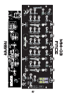
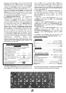
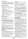
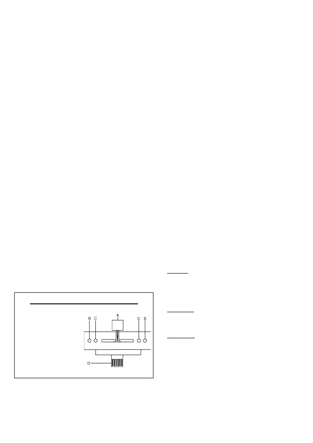
Replaceable Crossfader
1. Unscrew the outside FADER plate screws (B).
- Do not touch INSIDE
SCREWS (C).
2. Carefully remove old
Crossfader and unplug
CABLE (D).
3.Plug new Crossfader into
CABLE (D) and place back
into mixer.
4. Screw Crossfader to mixer
with the FADER PLATE
SCREWS (B).
(5)