PS-02USB 10" 3 CHANNEL STEREO MIXER
INTRODUCTION:
Congratulations on your purchase of a G
EMINI PS-02 USB (universal serial
bus)
PROFESSIONAL 10" 3 CHANNEL STEREO MIXER. This state-of-the-art mixer
features the latest technological advances & is backed by a T
HREE year war-
ranty, excluding the cross fader. The cross fader is backed by a separate 90
day warranty. Prior to use we suggest that you carefully read all the instruc-
tions.
FEATURES:
- 10" 3 stereo channel mixer
- 8 line inputs, including 6 RCA inputs, 3 convertible phono/line & 2 USB
ports
- Dual USB connectors
- USB connectivity allows mixes to be recorded directly to a compatible PC
or Mac without any additional hardware
- Mix audio files of any format directly from computer (via USB) with
records & CDs
- Both USB playback & recording function can be used simultaneously
- Master, record, & zone RCA outputs
- TRS ¼" balanced outputs
- Triple ground screw for easy connectivity
F
ACE:
- Removable face plate for user replaceable Rail Glide cross fader
- 3 band EQ kill switches with flash effect
- 3 band rotary line EQ with cut feature & rotary gain channel control
- Lighted push button cue section
- Rotary zone & balance controls
- Dual VU display with bright LED & mode switch
- Master volume fader control
F
RONT:
- TRS ¼" headphone output & Mic input
- Cue section with rotary Cue volume & Cue/PGM controls with Cue
Split/Mix switch
- Mic section with rotary Mic volume, high & low EQ controls
- Fader section with hamster/reverse, slope, & assign switches
PRECAUTIONS:
1. All instructions should be read before using this equipment.
2. To reduce the risk of electrical shock, do not open the unit. Please refer
all servicing needs to a G
EMINI-qualified service technician.
3. Do not expose this unit to direct sunlight or a heat source such as a radi-
ator or stove.
4. This unit should be cleaned only with a damp cloth. Avoid solvents or
other cleaning detergents.
5. When moving this equipment it should be placed in its original carton &
packaging. This will reduce the risk of damage during transit.
6. DO NOT EXPOSE THIS UNIT TO RAIN OR MOISTURE.
7. D
O NOT USE SPRAY CLEANERS OR LUBRICANTS ON CONTROLS, SURFACES OR
SWITCHES
.
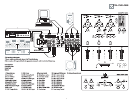
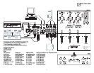
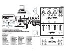
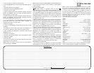
CONNECTIONS:
1. Before plugging this unit into any outlet, make sure that the
V
OLTAGE SELECTOR (1) is set to the proper voltage. To change the
selection, unscrew the hard plastic protective top with a Phillips head
screw driver. Then use a flat head screw driver to move the switch to the
proper selection (115 V/230 V).
2. Ensure that the P
OWER SWITCH (4) is in the OFF position prior to
making any connections. This unit comes with a P
OWER CORD (2).
Plug the P
OWER CORD (2) into the rear panel AC IN WITH FUSE (3) jack
before plugging it into a proper power source.
NOTE: LOCATED BY THE AC IN WITH FUSE (3) IS A 250 V FUSE TO
PROTECT AGAINST ELECTRICAL SURGES
. TO REPLACE THE FUSE, PLACE
A FLAT HEAD SCREWDRIVER INTO THE GROOVE LOCATED INSIDE THE AC
IN WITH FUSE
(3) & POP THE FUSE OUT. REPLACE THE FUSE WITH ONLY
A
250 V FUSE.
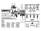
3. The PS-02 USB has six outputs located on the rear panel:
- The PS-02 USB features two USB P
ORTS (9, 11) to connect the
mixer to any Mac or PC USB (1.0 or greater) ports allowing the DJ
to either record a session onto any wave form editing software pro-
gram or add computer based DJing or audio programs, .MP3, .WMA, .WAV,
or .AIFF formatted music into the mix. The USB P
ORTS (9, 11) inputs
receive audio playback signals from a computer.
- The M
ASTER RCA OUTPUT (5) connects the mixer to your main
amplifier using standard audio cables with RCA-type connectors.
- The RECORD RCA OUTPUT (6) jacks can be used to connect the
mixer to the record input of your recording unit, thus enabling you
to record your mix with RCA cables.
- The Z
ONE RCA OUTPUT (7) jacks allow the connection of an addi-
tional amplifier with RCA cables.
- The TRS ¼" BALANCED OUTPUT (8) connects the mixer to your main
amplifier using standard cables with TRS ¼" connectors. We recom-
mend using balanced cables if the distance to the amplifier is ten feet
or more.
4. Headphones may be plugged into the ¼" jack located in the front
panel’s C
UE SECTION (21).
5. Microphones may be plugged into the ¼" jack located in the front
panel’s MICROPHONE SECTION (19).
6. The PS-02 USB has 3 C
ONVERTIBLE PHONO/LINE (PH/LN) RCA
inputs for channel (CH) 1, CH 2, & CH 3 located on the rear
panel. Facing the rear panel, the convertible RCA input for CH
1 is PH 1/LN 1 (18), for CH 2 is PH 2/LN 3 (16), & for CH 3
is PH 3/LN 5 (14). Using the PH/LN C
ONVERTERS, located just
below each input, you may convert the input from PH to LN &
vice versa. Plug the RCA's from your playable medium into each input to
be connected to their respective channels. The PH I
NPUTS only accept
turntables with a magnetic cartridge. The stereo LN I
NPUTS for CH 1 is LN
2 (17), for CH 2 is LN 4 (15), & for CH 3 is LN 6 (13) only accept line level
inputs such as a CD, DAT, M
INI DISC, etc. All RCA inputs require the prop-
er LN S
WITCH (32, 33, 34) setting.
7. When using (a) turntable(s), you will need to ground the RCA
cable(s) by screwing in the grounding fork(s) to the TRIPLE GROUNDING
SCREWS (GND) located in the rear panel of the PS-02 USB mixer. Attach
each PH ground lines to one of the GND. These are located to the right of
each PH/LN C
ONVERTER.
NOTE:
WHEN USING TURNTABLES, NOT ATTACHING A GROUND MAY CAUSE A SYSTEM
"HUM."
OPERATIONS:
1. Once all of your connections have been made in the rear panel, turn on
the mixer by pressing the P
OWER SWITCH (4).
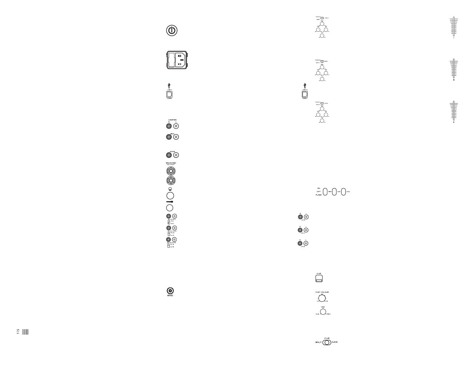
2. CH 1: To bring this channel into program output (PGM),
you must first decide which line will be in use. Use the CH 1
LN S
WITCH (32) to toggle from PH 1/LN 1 (18) to LN 2 (17) on
this channel. Once you've selected the proper line, slowly raise
the CH 1 F
ADER (23) to a comfortable level. You can further modify the
sound output of this channel by adjusting the rotary G
AIN, HIGH, MID, LOW
(29) controls located below the CH 1 LN SWITCH (32).
3. CH 2: To bring this channel into PGM, you must first decide
which line will be in use. Use the CH 2 LN SWITCH (33) to tog-
gle from PH 2/LN 3 (16) to LN 4 (15) on this channel. Once
you've selected the proper line, slowly raise the CH 2 F
ADER
(24) to a comfortable level. You can further modify the sound output of this
channel by adjusting the rotary G
AIN, HIGH, MID, LOW (30) controls located
below the CH 2 LN S
WITCH (33).
4. CH 3: To bring this channel in to PGM, you must first decide
which line will be in use. Use the CH 3 LN S
WITCH (34) to tog-
gle from PH 3/LN 5 (14) to LN 6 (13) on this channel. Slowly
raise the CH 3 F
ADER (25) to a comfortable level, once you've
selected the proper line. You can further modify the sound output of this
channel by adjusting the rotary G
AIN, HIGH, MID, LOW (31) controls located
below the CH 3 LN S
WITCH (34).
NOTE:
FOR OPTIMAL PERFORMANCE, BEGIN PROGRAM MIX WITH ROTARY GAIN CON-
TROLS SET TO MINIMUM & ROTATE IT TO THE COUNTER CLOCKWISE POSITION. MAKE
ALL ADJUSTMENTS IN SOUND OUTPUT WITH THE USE OF YOUR CH FADERS
(23, 24,
25),
ZONE (37), BALANCE (38), & MASTER VOLUME (26) CONTROLS. THIS WILL
PREVENT SIGNAL OVERLOAD
& DECREASE DISTORTION. ONCE YOU HAVE MODIFIED
YOUR SOUND
& WOULD LIKE TO INCREASE THE OUTPUT OF YOUR SOUND, THEN YOU
MAY ADJUST THE ROTARY GAIN CONTROL IF NEEDED
.
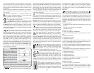
5. F
REQUENCY KILLS: There are two ways to kill, or cancel
out, frequencies, only on CH 2 (24) & CH 3 (25), using
the H
IGH, MID, & LOW FREQUENCY KILL SWITCHES (28). Each FREQUENCY KILL
SWITCH (28) has 3 positions: ON, OFF & FLASH. When you move the select-
ed F
REQUENCY KILL SWITCH (28) to the top ON position, the switch will stay
there, & the frequency will be killed. When you move the selected
F
REQUENCY KILL SWITCH (28) to the center position OFF the kill function is
not active, & the frequency will not be killed. When you move the selected
F
REQUENCY KILL SWITCH (28) to the bottom FLASH position & hold it there,
the frequency will be killed. Releasing the selected F
REQUENCY KILL SWITCH
(28) from the bottom position will bring it back to the center position &
the frequency will no longer be killed.
6. C
UE SECTION: By connecting a set of headphones to the ¼" jack in the
C
UE SECTION (21), you can monitor any or all channels.
- C
UE: Press the CUE BUTTONS (27) located above CH 1 (23), CH 2
(24), &/or CH 3 (25) to assign the CH(s) to be monitored in your head-
phones. The respective C
UE LED indicators will glow when in use.
- C
UE VOLUME: Use the front panel located rotary CUE VOLUME con-
trol to adjust the cue volume without changing the overall mix.
- CUE/MIX/PGM: By turning the front panel located CUE/MIX/PGM
rotary control counter clockwise you will be able to monitor the
assigned cue signal. Slowly turning the control clockwise to middle posi-
tion (M
IX) allows you to monitor your CUE signal mixed with PGM. Moving
the control clockwise to the right allows you to monitor PGM output.
- C
UE SPLIT/MIX: Use the CUE SPLIT/MIX switch to split the
audio input playing in your head phones. When the C
UE
4