


(44)
Congratulations on your purchase of a Gemini PS-03 10" 3 channel
stereo mixer. This state-of-the-art mixer features the latest technologi-
cal advances and is backed by a three year warranty, excluding the
cross fader. The cross fader is backed by a separate 90 day warranty.
Prior to use we suggest that you carefully read all the instructions.
- 10" 3 stereo channel mixer
- 6 line, 3 convertible phono/line, RCA inputs
- Master, record, & zone RCA outputs
- ¼" balanced outputs
- Triple ground screw for easy connectivity
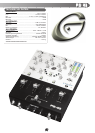
FACE:
- Filter assign switch
- Dry/Wet & resonance fader control
- Rotary Q factor control
- 3 filter recall & 3 band pass buttons with LED
- Dual mode push button for tempo on/off & cue effect
- Rotary tempo control
- 3 band rotary line EQ with cut feature & rotary gain channel control
- Removable face plate for user replaceable Rail Glide cross fader
- Lighted push button cue section
- Rotary zone & balance controls
- Dual VU display with bright LED & mode switch
- Master volume fader control
FRONT:
- ¼" headphone output & Mic input
- Cue section with rotary cue volume & CUE/PGM controls with cue split/mix switch
- Mic section with rotary Mic volume, high & low EQ controls
- Fader section with hamster/reverse, slope, & assign switches
1. All instructions should be read before using this equipment.
2. To reduce the risk of electrical shock, DO NOT OPEN THE UNIT.
Please refer all servicing needs to a Gemini-qualified service technician.
3. Do not expose this unit to direct sunlight or a heat source such as a
radiator or stove.
4. This unit should be cleaned only with a damp cloth. Avoid solvents or
other cleaning detergents.
5. When moving this equipment it should be placed in its original carton
and packaging. This will reduce the risk of damage during transit.
6. DO NOT EXPOSE THIS UNIT TO RAIN OR MOISTURE.
7. DO NOT USE SPRAY CLEANERS OR LUBRICANTS ON CON-
TROLS, SURFACES OR SWITCHES.
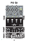
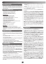
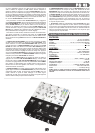
1. Before plugging this unit into any outlet, make sure that the VOLTAGE
SELECTION SWITCH (1) is set to the proper voltage. To change the
selection, unscrew the hard plastic protective top with a Phillips head
screw driver. Then use a flat head screw driver to move the switch to the
proper selection (115V/230V). Replace the hard plastic protective top,
and screw into the unit.
2. Ensure that the POWER SWITCH (4) is in the OFF position prior to
making any connections. This unit comes with a power cord. Plug into
the rear panel POWER CORD (2) jack before plugging it into a proper
power source.
NOTE: LOCATED BY THE POWER CORD (2) JACK IS A 250V FUSE (3) USED TO PRO-
TECT AGAINST ELECTRICAL SURGES. TO REPLACE THE FUSE, PLACE A FLAT HEAD
SCREWDRIVER INTO THE GROOVE LOCATED INSIDE THE POWER CORD JACK AND
POP THE FUSE OUT. REPLACE THE FUSE WITH ONLY A 250V FUSE.
3. The PS-03 has 4 outputs located on the rear panel:
- The MASTER RCA OUTPUT (5) connects the mixer to your main
amplifier using standard audio cables with RCA-type connectors.
- The BALANCED MASTER OUTPUT (8) connects the mixer to your
main amplifier using standard cables with 1/4" connectors. We recom-
mend using balanced cables if the distance to your amp is 10 feet or
more.
- The ZONE (7) output jacks allow the connection of an addi-
tional amplifier with RCA cables.
- The REC (6) output jacks can be used to connect the mixer to
the record input of your recording unit, thus enabling you to
record your mix with RCA cables.
4. Headphones may be plugged into the front panel-mounted
HEADPHONES (22) ¼" jack.
5. Microphones may be plugged into the front panel-mounted
MICROPHONE (21) ¼" jack.
6. The PS-03 has 3 CONVERTIBLE PHONO/LINE (PH/LN) RCA
INPUTS (10, 14, 18) located on the rear panel. Facing the rear
panel, the CONVERTIBLE RCA input on your right is for
PH1/LN1 (18). The convertible RCA input in the middle is for
PH2/LN3 (14). The convertible RCA input on your left is for
PH3/LN5 (10). Using the PH/LN CONVERTER SWITCHES (11,
15, 19), located just below each input, you may convert the PH
to LN and vice versa. Plug the RCA's from your playable medi-
um into each input to be connected to their respective CHAN-
NELS (CH). The PH INPUTS (10, 14, 18) only accept turntables
with a magnetic cartridge and require the PH switch setting as
indicated in the PH/LN CONVERTER SWITCHES (11, 15, 19).
The STEREO LN INPUTS (9, 10, 13, 14, 17, 18) only accept line
level inputs such as a CD, DAT, Mini Disc, etc and require the
LN switch setting as indicated in the PH/LN CONVERTER
SWITCHES (11, 15, 19).
7. When using (a) turntable(s), you will need to ground the
RCA
cable(s) by screwing in the grounding fork(s) to the TRIPLE
GROUND THUMB SCREWS (12, 16, 20) located in the rear
panel of the PS-03 mixer. Attach each PHONO ground line to
one of the TRIPLE GROUND THUMB SCREWS (12, 16, 20).
These are adjacent to each PH/LN CONVERTER SWITCH (11,
15, 19).
NOTE: WHEN USING TURNTABLES, NOT ATTACHING A GROUND MAY CAUSE A
SYSTEM "HUM."
1. Once all of your connections have been made in the rear
panel, turn on the mixer by pressing the POWER SWITCH (4).
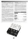
2. CH1: To bring this channel into program output (PGM), you
must first decide which line will be in use. Use the LN SWITCH
(23) to toggle from PH1/LN1 (18) to LN2 (17) on this channel.
Once you have selected the proper line, slowly raise the CH1
FADER CONTROL (29) to a comfortable level. You can further
modify the sound output of this channel by adjusting the rotary
GAIN (24), HIGH (25), MID (27), LOW (26) controls located
above the CH1 FADER CONTROL (29).
3. CH2: To bring this channel into PGM, you must first decide
which line will be in use. Use the LN SWITCH (30) to toggle from
PH2/LN3 (14) to LN4 (13) on this channel. Once you have
selected the proper line, slowly raise the CH2 FADER CON-
TROL (36) to a comfortable level. You can further modify the
sound output of this channel by adjusting the rotary GAIN (31),
HIGH (32), MID (34), LOW (33) controls located above the CH2
FADER CONTROL (36).
4. CH3: To bring this channel in to PGM, you must first decide
which line will be in use. Use the LN SWITCH (37) to toggle from
PH3/LN5 (10) to LN6 (9) on this channel. Slowly raise the CH3
FADER CONTROL (43) to a comfortable level, once you have
selected the proper line. You can further modify the sound out-
put of this channel by adjusting the rotary GAIN (38), HIGH (39),
MID (41), LOW (40) controls located above the CH3 FADER
CONTROL (43).
NOTE: FOR OPTIMAL PERFORMANCE, BEGIN PROGRAM MIX WITH ROTARY
GAIN (24, 31, 38) CONTROLS SET TO MINIMUM (ROTATE IT TO THE COUNTER
CLOCKWISE POSITION). MAKE ALL ADJUSTMENTS IN SOUND OUTPUT WITH
THE USE OF YOUR CHANNEL FADER CONTROLS (29, 36, 43), ZONE (51),
BALANCE (52), AND MASTER VOLUME (47) CONTROLS. THIS WILL PREVENT
SIGNAL OVERLOAD AND DECREASE DISTORTION. ONCE YOU HAVE MODIFIED
YOUR SOUND AND WOULD LIKE TO INCREASE THE OUTPUT OF YOUR SOUND,
THEN YOU MAY ADJUST THE ROTARY GAIN CONTROL IF NEEDED.
5. CUE: By connecting a set of headphones to the HEAD-
PHONE (22) jack, you can monitor any or all channels. Press
the CUE BUTTONS (28, 35, 42) for CH1 (29) through CH3 (43)
to assign the CH(s) to be monitored in your headphones. The
respective CUE LED indicators will glow when in use. Use the
front panel located rotary CUE VOLUME CONTROL (44) to
adjust the cue volume without changing the overall mix. By turn-
ing the front panel located CUE/MIX/PGM ROTARY CONTROL
INTRODUCTION:
FEATURES:
PRECAUTIONS:
IN THE USA ~ IF YOU EXPERIENCE PROBLEMS WITH THIS UNIT CALL GEMINI CUSTOMER
SERVICE AT
: 1 (732) 738-9003. DO NOT ATTEMPT TO RETURN THIS EQUIPMENT TO YOUR
DEALER.
CONNECTIONS:
OPERATING INSTRUCTIONS: