


(5)
(45) counter clockwise you will be able to monitor the assigned
CUE signal. Slowly turning the control clockwise to the middle
position allows you to monitor CUE mix with PGM. Moving the
control clockwise to the right allows you to monitor PGM output.
Use the CUE SPLIT/MIX (48) switch to split the audio input
playing in your head phones. Flip the CUE SPLIT/MIX (48)
switch to MIX mode to monitor your CUE/PGM signal mixed in
both headphones, while CUE/MIX/PGM (45) rotary control is in
the middle position. When the CUE SPLIT/MIX (48) switch is in
SPLIT mode, this enables you to monitor both outputs separately.
Notice one side of your headphones will play your CUE and the other
side will play PGM. This feature will only work properly if the
CUE/MIX/PGM (45) rotary control is placed at the middle position. If the
CUE/MIX/PGM (45) rotary control is set to CUE you will only here the
CUE signal playing on the left side of your headphones. If the
CUE/MIX/PGM (45) rotary control is set to PGM, the PGM will be the
only signal heard from the right side of your headphones.
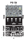
6. CROSS FADER SECTION: The CROSS FADER (46) allows you to
mix from one source to another. The CROSS FADER (46) in your unit is
removable and if the need arises can be easily replaced. Your Gemini
mixer comes with an RG-45 (RAILGLIDE™) DUAL-RAIL CROSS
FADER. RAIL GLIDE™ CROSS FADERS have internal dual stainless
steel rails that allow the slider to ride smoothly and accurately from end
to end. Also available is our RG-45 PRO (PROGLIDE™) DUAL-RAIL
CROSS FADER. This unique CROSS FADER features, a special curve
designed for scratch mixing. Just purchase one from your Gemini deal-
er and follow the instructions:
NOTE: DO NOT APPLY PRESSURE WHILE USING THE CROSSFADER. LIGHTLY GLIDE
THE CROSSFADER BACK AND FORTH. PRESSING DOWN ON THE CONTROLS CAN
BEND CONTACTS AND CAUSE A LOSS OF SOUND.
7. SLOPE CONTROL: The CROSS FADER SLOPE SWITCH (57
allows you to adjust the kind of curve the CROSS FADER (46) has. Flip
the CROSS FADER SLOPE SWITCH (57)down to make the slope
steep and cutting (perfect for scratching). Flip the CROSS FADER
SLOPE SWITCH (57) up to make the slope gradual and gentle.
8. REVERSE CONTROL: The CROSS FADER REVERSE SWITCH
(56) allows you to reverse the CROSS FADER (46) so that the left side
CH1 (29) or CH2 (36) is controlled by the right side of the CROSS
FADER (46) and the right side CH3 (43) is controlled by the left side of
the CROSS FADER (46). Flip the switch up to engage the REVERSE
(56) function, down to disengage the REVERSE (56) function.
NOTE: WHEN THE CROSS FADER REVERSE SWITCH (56) IS ACTIVATED (SWITCHED
UP), ONLY THE CROSSFADER (46) REVERSES. THE CHANNEL FADER, GAIN, FILTER
EFFECTS AND TONAL CONTROLS DO NOT REVERSE.
9. CROSS FADER ASSIGN: The CROSS FADER ASSIGN (58) switch
is used to place CH(s) on either side of the CROSS FADER (46). When
the ASSIGN (58) switch is in the top position, CH1 (29) & CH3 (43) are
assigned to the CROSS FADER (46). When the REVERSE (56) control
is not activated, CH1 (29) will be on the left and CH3 (43) will be on the
right. When the REVERSE (56) control is activated CH1 (29) will be on
the right and CH3 (43) will be on the left. When the ASSIGN (58) switch
is in the bottom position, CH2 (36) & CH3 (43) are assigned to the
CROSS FADER (46). When the REVERSE (56) control is not activated,
CH2 (36) will be on the left and CH3 (43) will be on the right. When the
REVERSE (56) control is activated CH2 (36) will be on the right and
CH3 (43) will be on the left. The unassigned CH1 (29) or CH2 (36) will
be controlled by their respective slide controls.
10. OUTPUT SELECTION CONTROL: Once you are comfortable with
the sound level of your music you may adjust the volume with the
MASTER VOLUME (47) slide control. You may adjust the volume of the
zone output with the ZONE (51) rotary control. You may also pan the
audio output from left to right with the BALANCE (52) rotary control.
11. MIC SECTION: Plug your main MIC into the MIC 1/4" INPUT (21)
located on the front panel. Connecting a microphone to the MIC 1/4"
JACK (21) allows voice amplification through the mixer to the stereo
through the MASTER RCA (5), ZONE (7), BALANCED (8) and REC (6)
outputs. This MIC is controlled by the MIC VOLUME (55), HIGH (54),
LOW (53) rotary controls. To activate this section, raise the level of the
MIC VOLUME (55). The rotary knob will click and a green LED will light
up to indicate that the MIC (21) is in use. To deactivate the MIC section
rotate counter clockwise until the knob clicks and the MIC VOLUME
LED will shut off.
12. VU METER: The PS-03 has a dual mode VU METER (50) that
allows you to monitor the decibel levels of CUE and PGM or LEFT and
RIGHT stereo levels of the MASTER output. With the VU MODE
SWITCH (49) you may monitor the output level of the CUE and PGM
when the switch is UP. When this mode is engaged the CUE will be
located on the left of the VU METER (50), while the PGM will be locat-
ed on the RIGHT. Or you can monitor the LEFT and RIGHT stereo deci-
bel levels of the MASTER OUTPUT when the VU MODE SWITCH (49)
is in the DOWN position.
NOTE: WHEN USING THE FILTER EFFECT, YOU MAY EXPERIENCE A TONAL BOOST
DURING A HIGH PASS THAT WILL SEND YOUR MASTER OUTPUT LEVELS INTO THE
BLUE (0 THROUGH +11), AS INDICATED IN YOUR VU METER (50). ADJUST THE CHAN-
NEL FADERS (29, 36, 43), IN ORDER TO PROTECT YOUR EQUIPMENT FROM A SYSTEM
OVERLOAD. TO BEGIN FILTER EXPERIMENTATION, START WITH A LOW PASS
(RESONANCE FADER (65) TO THE LEFT) WITH YOUR CHANNEL FADERS (29, 36, 43) AT
MID LEVEL. THEN MOVE SLOWLY THROUGH THE MID AND HIGH PASS TO EXAMINE
THE TONAL BOOST, SAFELY.
The PS-03 is equipped with DIGITAL SIGNAL PROCESSOR (DSP)
FILTER effects. This means you may augment the cut off frequency of
your program mix by filtering out the tonal boost located in the LOW,
MID, and/or HIGH frequency range. When an audio signal is processed
through the FILTER the unselected frequency(ies) will be muffled until it
is completely cancelled depending on the level of filtration. A wide range
of effects can be achieved with the PS-03 FILTER. Please follow these
instructions to operate the FILTER effects section of your mixer:
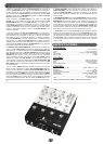
1. EFX ASSIGN: The PS-03 allows you to select the CH to be filtered,
while choosing multiple levels of filtration. Use the EFX ASSIGN (66)
switch to select a CH to filter by flipping the switch to the LEFT or
RIGHT until the EFX ASSIGN LED reaches the CH you wish to filter.
You may filter the audio outputs of CH1 (29), CH2 (36), CH3 (43), MIC
(21), or the MASTER (47). The blue LED indicator will show you which
CH will be filtered. When the CUE FILTER mode is activated the EFX
ASSIGN LED will blink to indicate which CH will be filtered in CUE. In
order to choose the frequency pass to FILTER press any of the 3 BAND
FILTER PASS (62) buttons located to the right of the CUE
FILTER/TEMPO ON (63) button.
NOTE: WHEN FLIPPING THROUGH CHANNELS AND THE DRY/WET FADER (59) IS AT
THE WET POSITION, AN AUDIBLE CLICK MAY BE HEARD IN PGM. TO PREVENT THIS
CLICK FROM BEING HEARD, LOWER THE CH SLIDES NOT IN USE TO THE CLOSED,
ZERO POSITION, PLACE THE DRY/WET FADER (59) IN THE DRY POSITION BEFORE
FLIPPING THROUGH THE CH WITH THE EFX ASSIGN (66).
2. FILTER PASS BUTTONS: When you press one of the frequency FIL-
TER PASS (62) buttons you will engage the pass, or direct the frequen-
cy to pass through the FILTER. You will notice this effect more when the
DRY/WET FADER (59) is at WET. You may filter up to 3 band frequen-
cies (LOW, BAND, & HIGH) at the same time. These filtration settings
can be saved into the filter memory via the FILTER RECALL (61) buttons
located on the left of the CUE FILTER/TEMPO ON (63) button. See FIL-
TER RECALL for more info.
3. FILTER RECALL: You may store up to 3 filtration settings into the
PS-03 filter memory with the use of the FILTER RECALL (61) section.
With this feature you will store various levels of filtration, as set in the
FILTER PASS (62) buttons, the DRY/WET (59), Q FACTOR (60),
RESONANCE (65), CUE FILTER/TEMPO ON (63) & TEMPO (64) con-
trol settings. To store these filtration settings, first set your filter as
instructed in the respective filter section instructions in the manual.
Once your filter has been set, press & hold one of the FILTER
RECALL (61) buttons for 2 seconds. The chosen FILTER RECALL
LED will flash when a filter setting is stored or the FILTER RECALL (61)
is in use. The LED will stop blinking and remain lit when this button is
not in use. The LED will remain lit to indicate that a filter setting is stored
into the filter memory.
Set your filter to be stored into another filter memory bank.
Repeat these steps to store filter settings into all of the filter memory
banks.
PPSS-0033
PPSS-0033
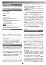
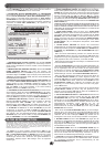
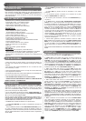
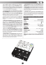
REPLACEABLE CROSS FADER
1. UNSCREW THE OUTSIDE FACE PLATE SCREWS ON THE LOWER HALF OF
THE MIXER. REMOVE THE FADER CAPS AND FACE PLATE.
2.UNSCREW THE FADER (B)
SCREWS. DO NOT TOUCH INSIDE
SCREWS (C). CAREFULLY REMOVE
OLD CROSS FADER AND UNPLUG
CABLE (D).
3. PLUG IN THE NEW CROSS FADER
INTO CABLE (D) AND PLACE BACK
INTO MIXER.
4. SCREW THE CROSS FADER TO
MIXER WITH THE FADER PLATE
SCREWS (B).
5. REPLACE THE LOWER HALF
FACE PLATE AND SCREW TO THE
MIXER. REPLACE THE FADER CAPS.
FILTER/EFX SECTION: