Page 5
IntroductionIntroduction
IntroductionIntroduction
Introduction
Congratulations on purchasing the Gemini UMX-3 VCA mixer. This state
of the art mixer is backed by a three year warranty, excluding crossfader
and channel slides. Prior to use, we suggest that you carefully read all the
instructions.
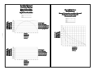
With VCA technology, audio is processed in a voltage-controlled amplifier
(VCA) removing it from the crossfader and channel slides giving them
extended life and reducing travel noise. The crossfader and channel slides
regulate the DC voltage that controls the VCA circuit. Additional
advantages of VCA technology include the ability to provide precise curve
adjustments for the crossfader and channel slides without sacrificing audio
quality. For additional information, refer to the diagrams on Page 3 for
crossfader adjustment and channel slide curve.
FeaturesFeatures
FeaturesFeatures
Features
•2 Stereo Channels
•3 Phono/Line Convertible, 1 Line, and 1 Mic Input
• Adjustable Input Assign Switches
• Channel Slide Curve Control
• Crossfader with Curve Control
• State of the Art Cue Section with Split
• Crossfader Reverse (Hamster) Switch
• Balanced and Unbalanced Master Outputs
• Zone and Record outputs
• Dual mode display
CautionsCautions
CautionsCautions
Cautions
1. All operating instructions should be read before using this equipment.
2. To reduce the risk of electrical shock, do not open the unit. There are
NO USER REPLACEABLE PARTS INSIDE. Please refer servicing to a
qualified service technician.
In the U.S.A., if you have any problems with this unit, callIn the U.S.A., if you have any problems with this unit, call
In the U.S.A., if you have any problems with this unit, callIn the U.S.A., if you have any problems with this unit, call
In the U.S.A., if you have any problems with this unit, call
1-732-969-9000 for customer service. Do not return equipment1-732-969-9000 for customer service. Do not return equipment
1-732-969-9000 for customer service. Do not return equipment1-732-969-9000 for customer service. Do not return equipment
1-732-969-9000 for customer service. Do not return equipment
to your dealer.to your dealer.
to your dealer.to your dealer.
to your dealer.
3. Do not expose this unit to direct sunlight or to a heat source such as a
radiator or stove.
4. This unit should be cleaned only with a damp cloth. Avoid solvents or
other cleaning detergents.
5. When moving this equipment, it should be placed in its original carton
and packaging. This will reduce the risk of damage during transit.
6. DO NOT EXPOSE THIS UNIT TO RAIN OR MOISTURE.
7. DO NOT USE ANY SPRAY CLEANER OR LUBRICANT ON ANY
CONTROLS OR SWITCHES.
Height AdjustmentHeight Adjustment
Height AdjustmentHeight Adjustment
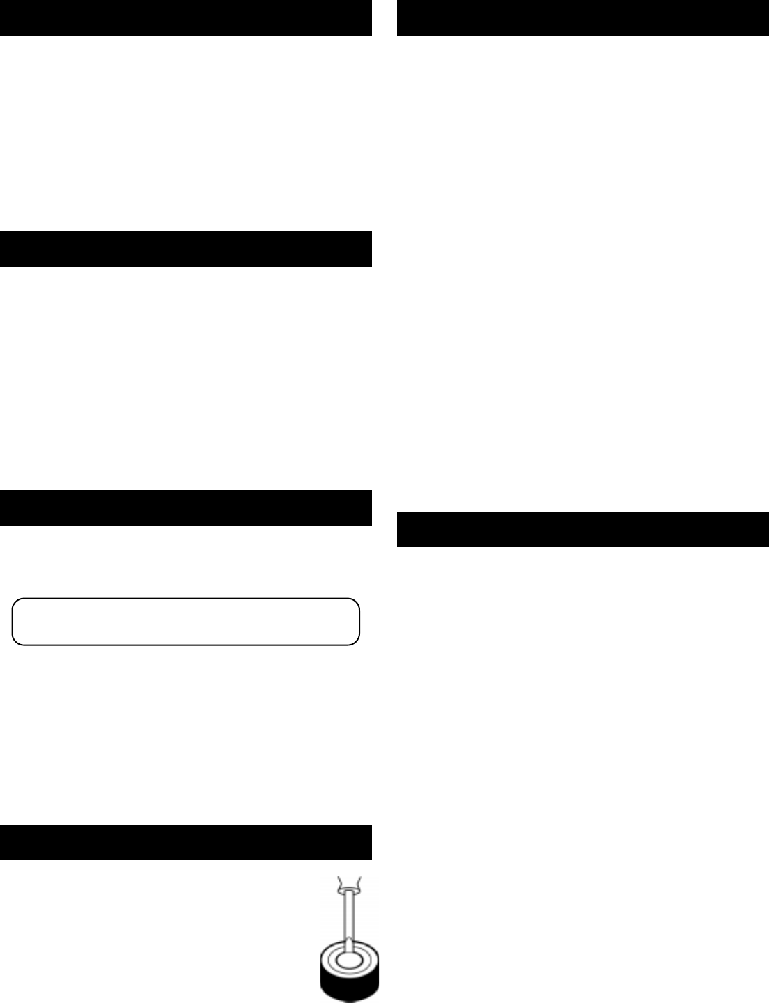
Height Adjustment
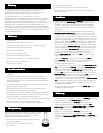
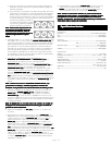
When using a UMX mixer with professional turntables, such as
the Gemini PT Series, you can make the mixer level with the
turntable by removing the mixer’s feet.
1. Place a small screw driver under the foot’s center anchor.
2. Gently pry the center anchor up and the foot will come off.
To replace the foot:
1. Place the foot on the mixer without the center anchor.
2. Replace the center anchor and push down on it to anchor
the foot to the mixer.
ConnectionsConnections
ConnectionsConnections
Connections
1. Make sure that the
POWER (1)POWER (1)
POWER (1)POWER (1)
POWER (1) switch is in the off position. The
POWER LED (32)POWER LED (32)
POWER LED (32)POWER LED (32)
POWER LED (32) will be off. This unit comes supplied with a 18 volt
AC adaptor. Plug the adaptor into the rear panel
power jack. Then plug
the adaptor into a proper power source.
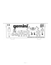
2. The UMX-3 is supplied with 4 sets of output jacks. The
BALANCED BALANCED
BALANCED BALANCED
BALANCED
MASTER OUTPUT (4)MASTER OUTPUT (4)
MASTER OUTPUT (4)MASTER OUTPUT (4)
MASTER OUTPUT (4) jacks are used to connect to your main
amplifier using standard cables with 1/4” connectors. We recommend
using the balanced amp outputs if the cables to your amp are 10 feet or
more.
BALANCED MASTER OUTPUTSBALANCED MASTER OUTPUTS
BALANCED MASTER OUTPUTSBALANCED MASTER OUTPUTS
BALANCED MASTER OUTPUTS have three separate
conductors, two of which are signal (positive and negative) and one
shield (ground). The balanced line uses a tip-ring-sleeve connection.
Tip = hot or positive (+), ring = cold or negative (-), and sleeve =
shield/ground. The
MASTER OUTPUT (5) MASTER OUTPUT (5)
MASTER OUTPUT (5) MASTER OUTPUT (5)
MASTER OUTPUT (5) jacks are unbalanced and
used to connect to your main amplifier. The
REC OUTPUT (7) REC OUTPUT (7)
REC OUTPUT (7) REC OUTPUT (7)
REC OUTPUT (7) jacks
can be used to connect the mixer to the record input of your recorder
enabling you to record your mix. The
ZONE OUTPUT (6) ZONE OUTPUT (6)
ZONE OUTPUT (6) ZONE OUTPUT (6)
ZONE OUTPUT (6) jacks allow
you to hook up an additional amplifier.
3. The
MIC (3)MIC (3)
MIC (3)MIC (3)
MIC (3) input (found on the rear panel)
OR OR
OR OR
OR the
MIC (35)MIC (35)
MIC (35)MIC (35)
MIC (35) input
(found on the front panel) accepts a 1/4" connector and balanced and
unbalanced microphones.
4. On the rear panel are 3 stereo
PHONO/LINE (9, 12, 13) PHONO/LINE (9, 12, 13)
PHONO/LINE (9, 12, 13) PHONO/LINE (9, 12, 13)
PHONO/LINE (9, 12, 13) inputs and 1
stereo
LINE (8) LINE (8)
LINE (8) LINE (8)
LINE (8) input. The
PHONO/LINEPHONO/LINE
PHONO/LINEPHONO/LINE
PHONO/LINE
SWITCHSWITCH
SWITCHSWITCH
SWITCH
(10) (10)
(10) (10)
(10) enables you to
set the
(9) (9)
(9) (9)
(9) input to Phono or Line. The
PHONO/LINEPHONO/LINE
PHONO/LINEPHONO/LINE
PHONO/LINE
SWITCHSWITCH
SWITCHSWITCH
SWITCH
(11) (11)
(11) (11)
(11)
enables you to set the
(12) (12)
(12) (12)
(12) input to Phono or Line. The
PHONO/LINEPHONO/LINE
PHONO/LINEPHONO/LINE
PHONO/LINE
SWITCHSWITCH
SWITCHSWITCH
SWITCH
(14) (14)
(14) (14)
(14) enables you to set the
(13) (13)
(13) (13)
(13) input to Phono or Line. The
phono inputs will accept only turntables with a magnetic cartridge.
GROUND SCREWS (2)GROUND SCREWS (2)
GROUND SCREWS (2)GROUND SCREWS (2)
GROUND SCREWS (2) for you to ground your turntables are located
on the rear panel. The stereo line inputs will accept any line level input
such as a CD player, a cassette player, etc.
5. Headphones can be plugged into the front panel mounted
PHONESPHONES
PHONESPHONES
PHONES
(36)(36)
(36)(36)
(36) jack.
OperationOperation
OperationOperation
Operation
1. POWER ON: Once you have made all the equipment connections to
your mixer, press the
POWER (1) POWER (1)
POWER (1) POWER (1)
POWER (1) switch. The power will turn on and
the
POWER LED (32)POWER LED (32)
POWER LED (32)POWER LED (32)
POWER LED (32) will light.
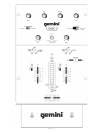
2. CHANNEL 1: The
GAIN (21)GAIN (21)
GAIN (21)GAIN (21)
GAIN (21) control allows you to individually adjust
the gain of the channel. Switch #
(24)(24)
(24)(24)
(24) allows you to select the
LINE 1/LINE 1/
LINE 1/LINE 1/
LINE 1/
PHONO 1 (13) PHONO 1 (13)
PHONO 1 (13) PHONO 1 (13)
PHONO 1 (13) or the
LINE 2/PHONO 2 (12) LINE 2/PHONO 2 (12)
LINE 2/PHONO 2 (12) LINE 2/PHONO 2 (12)
LINE 2/PHONO 2 (12) input. The
CHANNEL CHANNEL
CHANNEL CHANNEL
CHANNEL
SLIDE SLIDE
SLIDE SLIDE
SLIDE
(29)(29)
(29)(29)
(29) controls the input level of this channel.
3. CHANNEL 2: The
GAIN (23)GAIN (23)
GAIN (23)GAIN (23)
GAIN (23) control allows you to individually adjust
the gain of the channel. Switch #
(26)(26)
(26)(26)
(26) allows you to select the
LINE 3/LINE 3/
LINE 3/LINE 3/
LINE 3/
PHONO 3 (9) PHONO 3 (9)
PHONO 3 (9) PHONO 3 (9)
PHONO 3 (9) or the
LINE 4 (8)LINE 4 (8)
LINE 4 (8)LINE 4 (8)
LINE 4 (8) input. The
CHANNEL CHANNEL
CHANNEL CHANNEL
CHANNEL
SLIDESLIDE
SLIDESLIDE
SLIDE
(30)(30)
(30)(30)
(30)
controls the input level of this channel.
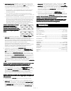
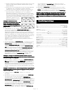
4. INPUT ASSIGN SWITCHES: You can adjust the position of the
INPUTINPUT
INPUTINPUT
INPUT
ASSIGN (24, 26)ASSIGN (24, 26)
ASSIGN (24, 26)ASSIGN (24, 26)
ASSIGN (24, 26) switches to move left to right, up and down
OROR
OROR
OR at a
45 degree angle. Make these adjustments with the power OFF.
1) Remove the channel slide, crossfader knobs and the 4 screws from
the sides of the lower face plate. Then remove the lower faceplate.
2) Remove the 2 screws in the corners of the assign switch plate.
Rotate the switch plate to the desired position, replace the screws
and tighten down.
3) To position the switch at a 45 degree angle, you need to reposition
the switch on the assign switch plate. First, remove the 2 screws in
the corners of the assign switch plate. Then, lift the switch plate up
and remove the 2 smaller screws next to the switch. Rotate the
switch plate to the right until the 45 degree holes align with the
switch holes, replace the screws and tighten down. Replace the
switch plate and tighten down.
1-732-738-9003