Page 6
NOTENOTE
NOTENOTE
NOTE
: Keep track of where you position: Keep track of where you position
: Keep track of where you position: Keep track of where you position
: Keep track of where you position
the input assign switches. To avoidthe input assign switches. To avoid
the input assign switches. To avoidthe input assign switches. To avoid
the input assign switches. To avoid
confusion, move the switch to a positionconfusion, move the switch to a position
confusion, move the switch to a positionconfusion, move the switch to a position
confusion, move the switch to a position
near the corresponding printing on thenear the corresponding printing on the
near the corresponding printing on thenear the corresponding printing on the
near the corresponding printing on the
faceplate.faceplate.
faceplate.faceplate.
faceplate.
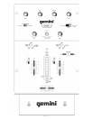
5. CHANNEL SLIDE CURVE SWITCHES: Use the 3 position
CHANNELCHANNEL
CHANNELCHANNEL
CHANNEL
SLIDE CURVE (28)SLIDE CURVE (28)
SLIDE CURVE (28)SLIDE CURVE (28)
SLIDE CURVE (28) switches to adjust the kind of curve the channel
slides have. Move the selected channel slide curve switch to the 6 (top)
position to make the increase in level gradual and even. Move the
channel slide curve switch to the 20 (center) position to make the
increase in level less gradual as you move channel slide up. Move the
channel slide curve switch to the 30 (bottom) position to make the
increase in level even less gradual, especially at the top of the slide.
6. CROSSFADER SECTION: The
CROSSFADER (34)CROSSFADER (34)
CROSSFADER (34)CROSSFADER (34)
CROSSFADER (34) allows the mixing
of one source into another. The left side of the
CROSSFADER (34) CROSSFADER (34)
CROSSFADER (34) CROSSFADER (34)
CROSSFADER (34) is
CHANNEL 1 and the right side is CHANNEL 2. The
CROSSFADERCROSSFADER
CROSSFADERCROSSFADER
CROSSFADER
CURVE (22)CURVE (22)
CURVE (22)CURVE (22)
CURVE (22) control allows you to adjust the kind of curve the
crossfader has. Move the
CROSSFADER CURVE (22)CROSSFADER CURVE (22)
CROSSFADER CURVE (22)CROSSFADER CURVE (22)
CROSSFADER CURVE (22) control to the
right to make the curve steep and cutting (perfect for scratching). Move
the
CROSSFADER CURVE (22)CROSSFADER CURVE (22)
CROSSFADER CURVE (22)CROSSFADER CURVE (22)
CROSSFADER CURVE (22) control to the left to make the curve
gradual and gentle. The
CROSSFADER REVERSE SWITCH (19)CROSSFADER REVERSE SWITCH (19)
CROSSFADER REVERSE SWITCH (19)CROSSFADER REVERSE SWITCH (19)
CROSSFADER REVERSE SWITCH (19)
allows you to reverse the crossfader so that CHANNEL 2 is controlled
by the left side of the crossfader and CHANNEL 1 is controlled by the
right side of the crossfader. When REVERSE is activated the
REVERSEREVERSE
REVERSEREVERSE
REVERSE
LED (33)LED (33)
LED (33)LED (33)
LED (33) will light.
NOTE: When the CROSSFADER REVERSE SWITCH (19) is activatedNOTE: When the CROSSFADER REVERSE SWITCH (19) is activated
NOTE: When the CROSSFADER REVERSE SWITCH (19) is activatedNOTE: When the CROSSFADER REVERSE SWITCH (19) is activated
NOTE: When the CROSSFADER REVERSE SWITCH (19) is activated
(moved to the right), only the crossfader reverses. The Channel Slides and(moved to the right), only the crossfader reverses. The Channel Slides and
(moved to the right), only the crossfader reverses. The Channel Slides and(moved to the right), only the crossfader reverses. The Channel Slides and
(moved to the right), only the crossfader reverses. The Channel Slides and
Gain do not reverse.Gain do not reverse.
Gain do not reverse.Gain do not reverse.
Gain do not reverse.
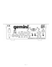
7. OUTPUT CONTROL SECTION: The level of the
MASTER OUTPUTMASTER OUTPUT
MASTER OUTPUTMASTER OUTPUT
MASTER OUTPUT
(4, 5)(4, 5)
(4, 5)(4, 5)
(4, 5) is controlled by the
MASTER (17) MASTER (17)
MASTER (17) MASTER (17)
MASTER (17) control. The
ZONE (16)ZONE (16)
ZONE (16)ZONE (16)
ZONE (16)
control adjusts the level of the
ZONE OUTPUT (6)ZONE OUTPUT (6)
ZONE OUTPUT (6)ZONE OUTPUT (6)
ZONE OUTPUT (6).
HINT: The zone
output is used by some DJs to run monitor speakers in their DJ booth.
You can also use it as a second ZONE or AMP output.
NOTE: The RECORD OUT (7) has no level control. The level is set by theNOTE: The RECORD OUT (7) has no level control. The level is set by the
NOTE: The RECORD OUT (7) has no level control. The level is set by theNOTE: The RECORD OUT (7) has no level control. The level is set by the
NOTE: The RECORD OUT (7) has no level control. The level is set by the
channel slides and the gain controls of the selected channel.channel slides and the gain controls of the selected channel.
channel slides and the gain controls of the selected channel.channel slides and the gain controls of the selected channel.
channel slides and the gain controls of the selected channel.
8. MIC CONTROL: The
MIC (15)MIC (15)
MIC (15)MIC (15)
MIC (15) level controls the level of the MIC.
9. CUE SECTION: By connecting a set of headphonesto the
PHONES (36)PHONES (36)
PHONES (36)PHONES (36)
PHONES (36)
jack, you can monitor the program output, each channel individually
or both channels together. The
CUE ASSIGN (20)CUE ASSIGN (20)
CUE ASSIGN (20)CUE ASSIGN (20)
CUE ASSIGN (20) allows you to select
what to monitor and has 3 positions. Move the
CUE ASSIGN (20)CUE ASSIGN (20)
CUE ASSIGN (20)CUE ASSIGN (20)
CUE ASSIGN (20) to
the left to monitor CHANNEL 1 and CHANNEL 2 in stereo. Move the
CUE ASSIGN (20)CUE ASSIGN (20)
CUE ASSIGN (20)CUE ASSIGN (20)
CUE ASSIGN (20) to the center position to monitor the program
(PGM) output. Move the
CUE ASSIGN (20)CUE ASSIGN (20)
CUE ASSIGN (20)CUE ASSIGN (20)
CUE ASSIGN (20) to the right to split the
signals from each channel so that CHANNEL 1 will be heard in one
earphone and CHANNEL 2 will be heard in the other earphone. While
the
CUE ASSIGN (20)CUE ASSIGN (20)
CUE ASSIGN (20)CUE ASSIGN (20)
CUE ASSIGN (20) is in the left or right positions (the CHANNEL 1
and CHANNEL 2 combinations), move the
CUE FADER (27)CUE FADER (27)
CUE FADER (27)CUE FADER (27)
CUE FADER (27) to the left
to isolate CHANNEL 1 and to the right to isolate CHANNEL 2. Move
the
CUE FADER (27)CUE FADER (27)
CUE FADER (27)CUE FADER (27)
CUE FADER (27) to the center to listen to both channels together
(split or in stereo).
10. DISPLAY: The peak hold, dual function
DISPLAY (31)DISPLAY (31)
DISPLAY (31)DISPLAY (31)
DISPLAY (31) indicates either
the
MASTERMASTER
MASTERMASTER
MASTER output left and right levels or the channel 1 and channel
2 levels. You can choose the option you want by pressing the
DISPLAY DISPLAY
DISPLAY DISPLAY
DISPLAY
(25)(25)
(25)(25)
(25) button.
NOTE: When the DISPLAY (31) is in the channel 1/channel 2 displayNOTE: When the DISPLAY (31) is in the channel 1/channel 2 display
NOTE: When the DISPLAY (31) is in the channel 1/channel 2 displayNOTE: When the DISPLAY (31) is in the channel 1/channel 2 display
NOTE: When the DISPLAY (31) is in the channel 1/channel 2 display
mode, by adjusting the individual channel gain, you can increase ormode, by adjusting the individual channel gain, you can increase or
mode, by adjusting the individual channel gain, you can increase ormode, by adjusting the individual channel gain, you can increase or
mode, by adjusting the individual channel gain, you can increase or
decrease the signal to match the other channel’s signal. The channel slidesdecrease the signal to match the other channel’s signal. The channel slides
decrease the signal to match the other channel’s signal. The channel slidesdecrease the signal to match the other channel’s signal. The channel slides
decrease the signal to match the other channel’s signal. The channel slides
and crossfader have no effect on the display readings.and crossfader have no effect on the display readings.
and crossfader have no effect on the display readings.and crossfader have no effect on the display readings.
and crossfader have no effect on the display readings.
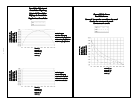
SpecificationsSpecifications
SpecificationsSpecifications
Specifications
INPUTS:
Mic......................................................................1.5mV 2Kohm balanced
Phono.....................................................................................3mV 47Kohm
Line....................................................................................150 mV 27Kohm
OUTPUTS:
Master (balanced)...........................................................0 dB 2 V 800 Ohm
Max.............................40 V Peak to Peak
Master/Zone (unbalanced)................................................0 dB 1V 400ohm
Max..............................20V Peak to Peak
Rec...........................................................................................225mV 5Kohm
GENERAL:
Gain.............................................................................................0 to -20dB
Frequency Response.................................................20Hz - 20KHz +/- 2dB
Distortion............................................................................................0.08%
S/N Ratio.........................................................................better than 80dB
Headphone Impedance.....................................................................16ohm
Power Source...............................................................115V/18V AC 0.75A
230V/18V AC 0.75A
Dimensions............................10”w x 14”h x 4.33”d (254 x 355 x 110 mm)
Weight.....................................................................................6.5 lbs (3 kg)