


H8070 Heirloom Telecaster-Style Guitar Kit
-15-
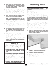
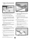
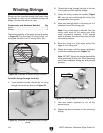
Figure 21. Headstock supported with shim.
Note: Drilling the holes deeper than
1
⁄2" could
result in drilling out through the top of the
headstock. Set the correct depth with the
depth stop on your drill press.
Shim
6. Place the pegboard face up on a level sur-
face, and use a dead blow hammer or a
dowel in a drill press to drive the six bushings
into the tuner mounting holes until they are
flush with the headstock (
Figure 22).
Figure 22. Installing bushings on headstock.
Note: If you have trouble inserting the bush-
ings, turn a drill bit by hand in the top of the
hole to ream it just enough to insert the bush
-
ing.
7. Turn the neck over, insert the tuners into
the bushings, and mount them with the 2.1 x
12mm screws.
Wiring Pickups
This guitar comes with a control plate that has
most of the components soldered in place. You
only need to solder the pickup wires onto the three
way switch and volume control. If done incorrectly,
the soldering can damage the components. If you
are unsure of your skills, do your research, prac-
tice on scrap wires, or take it to a professional.
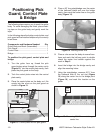
Components and Hardware Needed: Qty
Guitar Body .......................................................
1
Control Plate ......................................................
1
Pick Guard .........................................................
1
Pick Guard Pick Up ...........................................
1
Bridge ............................................................... 1
Output Jack .......................................................
1
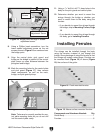
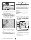
To wire the pickups:
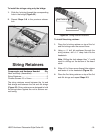
1. Thread the pick guard pickup and bridge
pickup wires through the channels and holes
in the control plate cavity as shown in
Figure
23. (Also, refer to the Wiring Diagram on
Page
29 and the Electrical Photos on
Pages 27-28.)
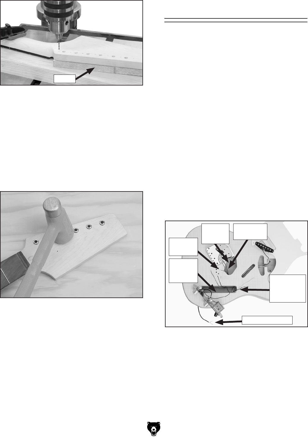
Figure 23. Wires threaded through body.
Audio Jack Wire
Ground
Wire
Pick Guard
Pickup
Wires
Bridge
Wires
Control
Plate
Cavity
Bridge
Cavity
2. Thread the ground wire through the hole in
the control plate cavity and into the bridge
cavity (
Figure 23).
3. Push the audio jack wire out through the hole
in the end of the body.