-16-
H8070 Heirloom Telecaster-Style Guitar Kit
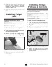
4. Solder the pickup wires to the volume and
three way switch as shown in the
Wiring
Diagram on Page 29 and the Electrical
Photos on Pages 27-28.
5.
Solder the audio jack wires onto the output
jack.
Installing Output
Jack
Components and Hardware Needed: Qty
Output Jack .......................................................
1
Output Jack Cover .............................................
1
Chrome Screws 3.1 x 12mm
.............................. 2
To install the output jack:
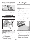
1. Thread the output jack onto the jack cover.
2. Place the output jack cover in the jack cavity,
and mark the mounting holes.
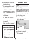
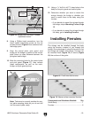
3. Using a
1
/16" drill bit, drill
3
/8" holes at a 45º
angle into the body as shown in
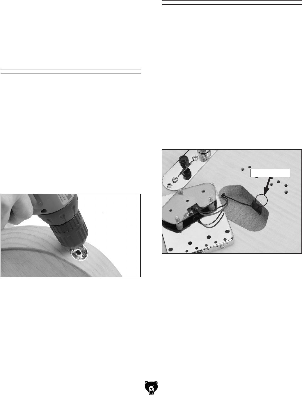
Figure 24.
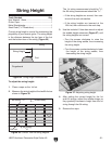
Figure 24. Drilling output jack mounting holes.
4. Mount the output jack cover with two
3.1 x
12mm screws.
Installing Bridge,
Pickups & Controls
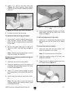
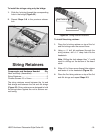
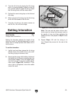
Figure 25. Ground wire above bridge cavity.
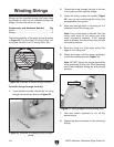
3. Secure the bridge with the 3.5 x 25mm
screws, and fasten the control plate with 3.1
x 12mm
screws.
To reduce humming in your amp, the ground wire
must contact the bridge plate.
Components and Hardware Needed: Qty
Guitar Body ....................................................... 1
Pick Guard .........................................................
1
Chrome Screws 3.5 x 25mm .............................
4
Chrome Screws 3.1 x 12mm
.......................... 10
To install the control plate and pickups:
1. Tape the ground wire so the exposed por-
tion curls over the bridge cavity as shown in
Figure 25.
2. Place the bridge into the cavity so the plate
makes contact with the wire.
Ground Wire


