


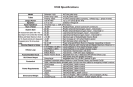
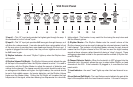
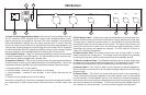


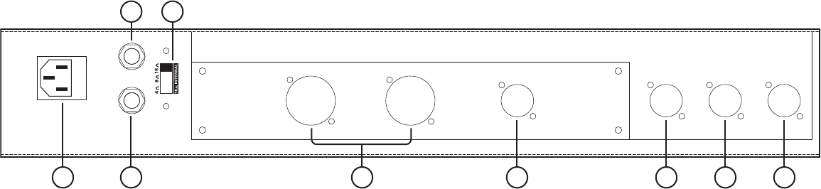
1) Power Cord Receptacle/Fuse Holder: Insert the AC cord (provided) rmly into
the AC connector. NOTE: Replace the AC power cord if protective jacket is dam-
aged or ground pin is damaged or removed. The fuse is located in a housing just
below the receptacle. Replace only with same type and size. To remove the fuse,
remove AC power cord and pull out on the tab above the fuse symbol located on the
fuse carriage. Place the new fuse in the carriage clip and re-insert. NOTE: To prevent
an electrical hazard, DO NOT replace fuse without using the fuse carriage. Replace
the fuse carriage if lost or damaged before re-inserting the AC power cord.
2 & 3) Speaker Outputs—These 1⁄4” jacks are provided to connect the internal and/
or external speakers to the V50 amplier. The V50 amplier should never be oper-
ated without a speaker plugged into a speaker jack.
4) Impedance Selector—This switch is used to select the appropriate impedance,
and is important in achieving the desired results from the V50 ampliers. The correct
impedance should be selected using the Impedance Selector Switch as follows:
a. Internal speaker only: 16 ohm setting
b. Internal speaker + external 16 ohm speaker: 8 ohm setting
c. Internal speaker + external 8 ohm speaker: 4 ohm setting, although it’s not
matched
d. External 16 ohm speaker alone: 16 ohm setting
Incorrectly “mismatching” the amp to the speaker should not damage the amplier,
but would result in lower output powers, and could result in shorter output tube
life.
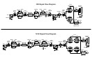
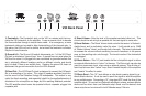
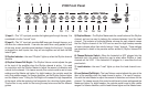
5) EL34 Output Tubes—These power tubes were selected to provide the best com-
bination of performance and tube life, and shouldn’t require adjustment to their bias.
The amp uses a mixed-bias system which is a combination of xed and self-bias
techniques to give the user the best of both worlds. The result is that the amp will
control its own bias to a certain point, but without the typical reduction in power
associated with normal self-biased amp designs. The V50 uses two EL34s in a
“push-pull” amplier conguration.
6) Phase Inverter Tube—The phase inverter tube uses a single 12AX7 in what’s
called a long-tail pair conguration. This results in the most signal swing possible
for driving a power amp, and the most symmetrical drive capability, as well.
7) Effects Loop/Boost Tube—The Defender ampliers use an all-tube effects loop
to preserve the tube sound through the signal path. This single tube is used for both
the Effects Loop Send/Return and the footswitchable Volume Boost circuit.
8) Preamp Tube 2—This 12AX7 is used on both channels, but has the biggest im-
pact to the lead channel since it has the additional stage required for the very large
amount of gain.
9) Preamp Tube 1—This 12AX7 is the input tube, and as such, is the most likely to
cause microphonic problems, especially in the lead channel, and it is also shared
by both channels. If tube feedback occurs, it can usually be corrected by swapping
this rst tube with one of the other tube locations, since they have less gain following
them and are less prone to feedback. The rst tube also has the greatest affect on
the “cleaned up” tone of the amp, i.e. the tone when the guitar is turned down.
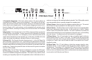
41&",&30651654
83.473.4
"41&",&3.645#&1-6((&%*/
*.1&%"/$&4&-&$503
- - "9 "9 "9 "9
V50 Bottom
50 28
EL34 EL34