


15
Owner’s Manual
Owner’s Manual
LEVEL SET (PFL) taps the channel signal
before the fader. If you have a channel’s fader
set way below “U” (unity gain), SOLO won’t
know that and will send a unity gain signal to the con-
trol room, headphones, and meters. That may result in a
startling level boost at these outputs, depending on the
position of the SOLO [46] level knob.
In a nutshell, soloed channels are sent to the SOURCE
[42] mix, that ultimately feeds your control room,
headphones, and meters. Whenever SOLO is engaged,
all SOURCE selections (MAIN MIX, 1–2, 3–4 and TAPE)
are defeated, to allow the soloed channel to do just that
— SOLO!
28. –20 (SOLO) LED
An LED that does two completely different things!
This saves space, but requires some explanation.
First, the “–20” part: Often referred to as “signal activ-
ity,” this LED will fl icker in time with the signal present
in that channel. It’s handy for confi rming that a channel
is indeed active, and may also lend a clue as to what the
signal is. For instance, a kick drum will cause the LED
to pulse in time with the drum, and a synth pad will
cause it to glow a bit more steadily.
Now for the “SOLO” part: When a channel’s SOLO [27]
switch is engaged, this LED will glow steadily. It will
also be brighter than it would be as a –20 indicator. In
conjunction with the RUDE SOLO LIGHT [47], you can
fi nd a rogue SOLO switch very quickly.
29. OL (MUTE) LED
Another LED that does two different things!
First, the “OL” part: “OL” means overload, or clip. You
don’t want that to happen. Ever. Clipping can happen
to any mixer — it’s the point where the signal’s volt-
age tries to exceed the supply voltages that power the
circuitry. This OL LED will come on just before clipping,
so if you see it, take immediate action: Perform the
Level-Setting Procedure. If that doesn’t help, check for
excessive use of EQ boost or fader gain. Like the –20
LED, it will fl icker in time with that channel’s signal.
Now for the “MUTE” part. Assuming your levels are
set correctly, the OL LED will never come on as a result
of clipping. That’s pretty boring. So, to liven things up,
this LED will glow steadily when that channel’s MUTE
switch is engaged.
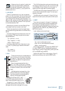
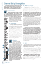
Here is a quick reference to these LEDs:
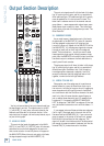
30. MUTE
Engaging a channel’s MUTE switch provides the same
results as turning the fader all the way down: Any chan-
nel assignment to L/R, 1-2 or 3-4 will be interrupted. All
the post AUX sends will be silenced, as will the DIRECT
OUT [5] signals on channels 1 through 8. And of course,
that fun-loving OL (MUTE) LED [29] will commence
to glow. The PRE AUX sends, channel INSERT [4]
send and SOLO [27] (in LEVEL SET (PFL) mode) will
continue to function during MUTE.
Depending on the audio content in a channel, engag-
ing its MUTE switch may cause a slight popping sound.
This is not a problem within the mixer, and it can be
avoided: Simply engage the LOW CUT [34] switch on
each channel (unless its low frequency content is vitally
important, such as a kick drum or bass guitar). LOW
CUT eliminates subsonic debris, which causes the pop,
and its effect is usually transparent.
31. PAN
PAN adjusts the amount of channel signal sent to the
left versus the right outputs. PAN determines the fate
of the L/R assignment, subgroups 1–2 and 3–4, and the
SOLO [27] (in NORMAL (AFL) mode).
With the PAN knob hard left, the channel signal will
feed the left main mix, subgroup 1, subgroup 3 and left
NORMAL (AFL) solo mode (assuming their assignment
switches are engaged).
With the knob hard right, the channel signal feeds
the right main mix, subgroup 2, subgroup 4 and right
NORMAL (AFL) solo mode.
With the PAN knob set somewhere in-between left
and right, the signal will be divided between the left and
right buses.
The PAN knob behaves a little differently for the ste-
reo channel strips. Since there is a left and right input
on these channels, the PAN knob controls the relative
balance between the left and right sides, just like the
balance control on your stereo system at home.
Stereo Sources
Use channels 9-16 to connect stereo sound sources. If
you must use the mono channel strips (1-8) for stereo
sources, follow this standard convention: Always plug
the left signal into an “odd” channel (1, 3, 5, etc.) and
the right signal into the adjacent “even” channel (2, 4, 6,
etc.). Then pan the odd channel hard left and the even
channel hard right.
Name Color Flickering Glowing
–20 (SOLO) green signal present channel soloed
OL (MUTE) red channel clipping channel muted