13
fate befalls the cord, you can use any standard
IEC cord like those found on most professional
recorders, musical instruments and computers
(for example Radio Shack #278-1257 {6-ft} or
#278-1261 {12-ft.}). NOTE: Disconnecting the
plug’s ground pin can be dangerous. Don’t do it.
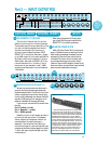
FUSE
The CR-1604 is fused for your (and its own) pro-
tection. If you suspect a blown fuse, disconnect the
power cord, pull the fuse drawer just below the AC
receptacle and replace the fuse with a 1-amp SLO
BLO fuse (or 1/2-amp SLO BLO fuse if the unit is a
230V model). 230V models have a bright red
230V sticker both on the shipping box and on
the mixer itself. If two fuses blow in a row, some-
thing is very wrong. Call our toll-free number and
find out what to do.
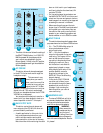
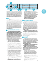
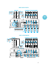
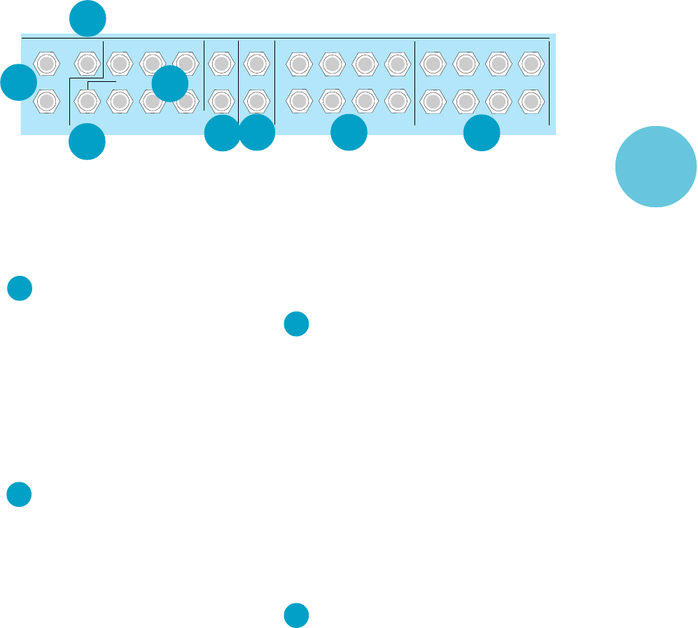
CHANNEL ACCESS, TIP=OUT, RING=IN
This is where you connect series processors
such as compressors, equalizer, de-essers, or filters.
Since most people don’t have more than a few of
these gadgets, we’ve included connections for just
the first eight channels. If you want to use this kind
of processing on Channels 9–16, simply plug into
and out of the device before you plug into the
CR-1604 channels. Connecting a processor here
will affect only the associated channel.
• Tip=output (send to external device),
Ring=input (return from external device)
• The insert points are after the mic preamps,
channel faders and equalizers (Post-Fader/
Post-EQ). This can be modified with a little
technical knowledge found on pages 33–34.
• CHANNEL ACCESS outputs are low-imped-
ance (120-ohm) and are capable of driving all
processors (except Cuisinart food processors).
• For best results the device should be capable
of at least +18dB input/output (any profes-
sional unit). Do not use “stomp box”-style
devices. They simply can’t keep up with the
operating level needed to match CR-1604
performance.
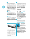
• The CR-1604’s CHANNEL ACCESS jacks are of
a special design that gives more flexibility than
regular jacks. What kind of plug you use and
how far you plug it in varies the function of
CHANNEL ACCESS jacks For example, a
mono plug inserted only to the first click does
not interrupt the master (main outputs,
headphone output, ALT-3/4 outputs). Plugged
all the way in, it becomes a direct out and
interrupts. This may seem weird at first, but
it’s the way. See page 16 for a picture
describing the plug and inserts.
AUX RETURNS TO MASTER
This is where you connect the output of your
effects devices or, in some cases, return the signal
of a multitrack tape machine/mixdown deck.
Many mixers simply have a passive input cir-
cuit for AUX returns. We have active input gain
circuitry which allows use of a wider range of ex-
ternal devices. The circuits will handle stereo or
mono unbalanced signals at instrument level or
–10dBV to +4dBu.
These eight inputs can be used for a vari-
ety of effects. (For more detailed information
on functions and their relationships to practi-
cal application in the production of your
music, see the Applications Guide in our In
Your Face magazine.
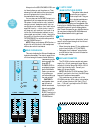
BUS INSERT
These are the send and receive jacks for
inserting an effect such as final compression,
limiting or EQ into the Main Left/Right Buses.
Inserting a processor here will affect your
entire mix. See page 16 for a picture describ-
ing the plug and inserts.
The BUS INSERTS can also be used as an
output with no interuption to signal.
NOTE: The BUS INSERTS are pre-main
faders. If you are using them for output, make
sure the connecting device has some way to
adjust incoming level.
• Tip=output (send to external device),
Ring=input (return from external device)
• The BUS INSERT is before the Master fader
controls and after the main L/R mix amps.
• Inputs and outputs are unbalanced and
designed to work with pro devices with at least
18dB of input/output.
• The BUS INSERT can also be used as a tape
out if plugged in the first “click”. Master
adjustments will not affect level.
LEFT
RIGHT
BUSS INSERT
LEFT
RIGHT
ALT 3/4 OUT
3
6
2
5
1
4
MONITOR
LEFT
RIGHT
AUX OUTPUTSMONOBAL MAIN OUT
4
8
3
7
2
6
1
5
CHANNEL ACCESS TIP=OUT RING=IN
4321
AUX RETURNS
L
R
27
26
33
34
32
31
2930
28
27
INPUT
OUTPUT
POD
28
29


