


32
Technical Information
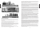
Valve compliment: Three ECC83s (12AX7s) in the pre-amp and a quartet of EL34 power valves
working in push-pull. All valves are of the highest quality available and are subjected to meticulous grading
and testing processes.
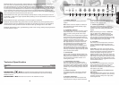
The way the three ECC83s (V1, V2 & V3) in the pre-amp are utilised is as follows:
V1 acts as the pre-amp gain stage for the High Treble and Normal channels - each half of the valve (the
ECC83 being a dual-triode) acting as a dedicated gain stage for each channel.
V2 is common to both channels, which are passively summed before reaching this valve. The first half of V2
acts as a common second gain stage, boosting the combined signal, and then directly driving the second
half of the valve which is configured as a cathode follower
.
The cathode follower is a unity gain device which
acts as a buffer, providing a low impedance signal to drive the tone network.
Tonal Note 1: The second gain stage of the 1969 circuit we’ve faithfully reproduced boasts an extra
cathode bypass capacitor which boosts upper-mids and top-end.
V3 acts as the amplifier's phase-splitter. This device divides the signal into two halves that are 180 degree
out-of-phase with each other, and then feed the 1959's push-pull output stage.
Tone Circuit: In typical Marshall fashion, the shared tone network of this handwired 1959 re-issue is
post gain, passive and interactive - the latter simply meaning that the settings of the Bass and Treble controls
affect the amount of mid-dip available via the Middle control.
Tonal Note 2: The Middle control is a 10% log pot, unlike the linear one found in the regular production
1959SLP. This greatly changes the dynamic of the whole tonal network and the interaction of its controls.
Components: Where possible we have gone back to the original suppliers for all components, to
maintain the highest quality - including, as per the original, a U-clamp mounted choke as opposed to the
fully-shrouded, stand-up smoothing choke used in the majority of Marshall valve amplifiers. Also included is a
custom-built 50µF single can, smoothing capacitor. These are just two examples of the many steps we have
taken in order to ensure maximum authenticity.
Tag Boards: The tag boards used in your handwired re-issue is exactly the same as that in the original in
terms of thickness and matrix pitch. The material we're using is made exclusively for us and is registered with
UL as ‘Marshall EM42 brown’. The reason we didn’t use a board with the exact same chemical composition
as in the original units is because that material doesn't pass current safety legislation regarding flammability.
Transformers: As you are no doubt aware, the output and mains transformers are vital components in
an amplifier as they influence performance, sound and feel. Consequently, we worked extremely closely with
our associates in Dagnall’s R&D department in order to duplicate the original transformers. To do this we
spent a great deal of time and attention studying and analysing the constructional methods and materials
used in both transformers so we could match everything as closely as possible and also ensure that the all-
important electrical characteristics and performance were identical.
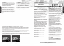
Output Transformer: Just like the 1.5" original, it is an exact replica in terms of both performance and
dimensions, the re-issue transformer is upright-mounting and sits entirely above the chassis. To be exact,
this transformer is a C1998 which has a specification date of August 1967
Tonal Note 3: In the vast majority of Marshall valve amplifiers it is a standard design trait that the negative
feedback (a circuit that drops the output impedance and thus controls the damping factor of the powerstage)
applied around the amplifier is taken from the 8 Ohm tap on the output transformer. Doing this sets the
power-amp up for a certain amount of damping that is independent of where you have the amplifier's
impedance selector set. This means that, regardless of whether you use a 16, 8 or 4 Ohm cabinet, the
damping on the speakers is the same.
This said, as is the case with quite a number of ‘Plexi’ era 100 Watt heads, the negative feedback on the
original 1969 circuit we've used for this reissue is taken off the actual speaker output itself. This means that
the lower the impedance setting, the lower the damping factor - and the lower the damping factor is, the
more loose and more resonant the sound. Consequently, if you’re using a 4 x 12" cabinet loaded with
16 Ohm speakers that offers 16 Ohm and 4 Ohm mono inputs (e.g.: the Marshall 1960A, 1960B, 1960AV or
1960BV cabinets), the 4 Ohm input will be more loose and more resonant on the low end, while the 16 Ohm
input will be tighter and more controlled.
Not surprisingly, of the ‘tonally significant’ variants mentioned in this manual, this one is probably the most
significant.
Mains (Power) Transformer: While the original transformer is large, the custom-made Dagnall re-
issue has been made even larger in order to satisfy strict, current-day safety legislation. Just like the original,
the re-issue transformer is what is called a ‘drop through, half-shroud’, which sits horizontally as opposed to
vertically. As with the output transformer, we went to great lengths to ensure that its performance mirrors that
of the original, paying particular attention to exactly replicating an effect called ‘regulation’ - which is the way
that the voltage from the transformer that feeds the valve circuitry varies according to load. In terms of the
concentric design and performance, this transformer embodies the performance of the 1203-80 original
specification first drawn up for us by Drake in February 1967. The original was a 2.5" transformer. Due to the
aforementioned modern legislations, the reissue is 3".
T
onal Note 4:
This circuit has the same filtering on the H.T
. (high voltage DC, a.k.a. the B+ voltage) line as
later versions, a factor that contributes to the 1959HW having a tighter sound than earlier versions.
Note: The 1959HW incorporates 47nF/630V capacitors fitted in parallel with each of the four diodes in the
bridge rectifier circuit. These are present for today’s approval requirements that necessitate a reduction in
electrical interference that may be generated and put back on the mains electricity supply. The addition of
these capacitors has no sonic impact.
ENGLISH
ENGLISH
CHOKE
SINGLE CUSTOM-BUILT
50µF CAPACITOR
EL34 POWER
VALVES
V1 V2 V3
MAINS
TRANSFORMER
OUTPUT
TRANSFORMER
ECC83 VALVES