


54
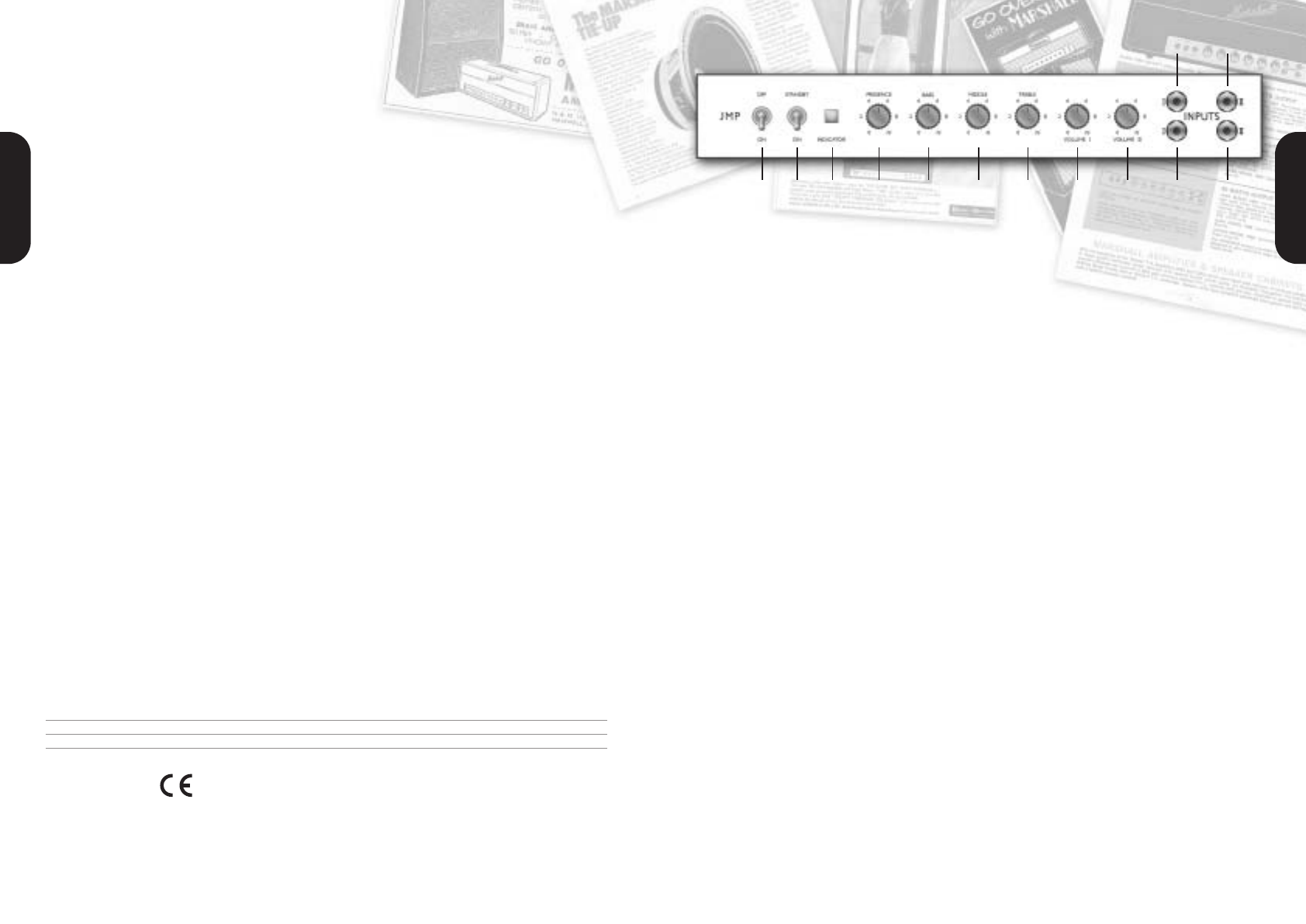
1. POWER SWITCH
This is the On/Off switch for mains power to the
amplifier.
Note: Please ensure the amplifier is switched off
and unplugged from the mains electricity supply
whenever it is moved.
2. STANDBY SWITCH
The Standby Switch is used in conjunction with the
Power Switch (item 1) to ‘warm up’ the amplifier
before use and to prolong the life of the output
valves.
When powering up the amplifier always engage the
Power Switch first, leaving the Standby switch on
‘Standby’. This allows the application of the voltage
required to heat the valves to their correct
operating temperature - hence the switches name.
After approximately two minutes the valves will
have reached the correct operating temperature
and the Standby Switch can be engaged.
In order to prolong valve life, the Standby Switch
alone should also be used to turn the amplifier on
and off during breaks in a performance. Also, when
switching off, always disengage the Standby Switch
prior to the main Power Switch.
3. INDICATOR
This 6.3 Volts incandescent filament indicator will
light up when your amplifier is receiving the correct
mains power and is switched on. It will not be lit
when the amplifier is switched off and/or is not
receiving mains power.
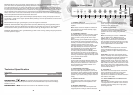
4. PRESENCE CONTROL
This control operates in the 1959HW’s power
section and adds high frequencies to your sound
by altering the power amplifier’s negative feedback.
Turning this control clockwise adds more edge and
‘sparkle’ to your sound, making it crisper and more
cutting.
5. BASS CONTROL
This adjusts the bottom end, turning it clockwise
increases the amount of low frequencies in the
sound.
6. MIDDLE CONTROL
This adjusts the level of those all-important mid-
range frequencies. Turning it clockwise increases
the mids and fattens your sound, giving it more
punch. Turning it anticlockwise reduces the mids,
producing a more ‘scooped’ tone.
7. TREBLE CONTROL
This adjusts the top-end. Turning it clockwise
increases the amount of high frequencies (treble)
present in the sound, making your guitar tone
brighter.
Note: The following four controls - PRESENCE
(item 4), BASS (item 5), MIDDLE (item 6) &
TREBLE (item 7) - are all shared, meaning that
they all work on both Channel I and Channel II.
They are highly interactive and altering one control
can change the way the other two behave. For this
reason, experimentation is recommended.
8. VOLUME I
This controls the overall output level of Channel I,
turning it clockwise increases the volume. This
channel is voiced for a higher treble response than
Channel II.
Tonal Note 5: The value of the capacitor across
Volume I is 0.005µF. This rather large value makes
this channel aggressive and bright at relatively low
settings. Many players bridge (see page 6 for
details) Channels I and II (which has a darker, less
aggressive tone) in order to have more control over
their overall tone. Many earlier versions of the 1959
(from 1965 to 1967) used a 100pf capacitor across
Volume I which gives a less aggressive sound at all
volume levels less than 8.
9. VOLUME II
This controls the overall output level of Channel II,
turning it clockwise increases the volume level.
This channel is voiced for a ‘normal’, flatter
response and is labelled as the ‘Normal’ Channel in
later versions of the 1959.
10. HIGH SENSITIVITY INPUT FOR
CHANNEL I
This is the ‘high sensitivity’ guitar input for Channel I
- the brighter of the two channels - and is the most
commonly used input.
Always use a high quality
screened guitar lead.
1959HW Front Panel
ENGLISH
ENGLISH
1 2 3 4 5 6 7 8 9 11 13
10 12
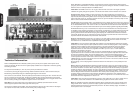
Chassis: We are using a box-section chassis made from 16 gauge mild steel with butt-welded corner
joints. The steel is also passivated giving lifelong resistance to corrosion.
Our original chassis has a lot of extra holes drilled in it that weren't used. No doubt these existed because
the same exact chassis was also used for other products made at the time. The most noticeable ‘extra hole’
is one on top for a fourth ECC83 and on our reference unit, this particular hole has been covered up with a
disc of steel that's been riveted into the two screw holes that would have been used to secure the valve
holder, were it there. For the sake of authenticity we have copied all the holes on our reference chassis and
have even duplicated the aforementioned circular steel cover!
Front Panel: Extra thick, gold coloured Plexiglas (actually Perspex, causing some people to refer to it
as ‘Perplexi!’) - exactly as the original. Specific details pertaining to the front panel features can be found on
page 5 of this manual.
Rear Panel: Once again, gold Plexiglas - just like the original we referenced.
Cabinet Construction: High-grade, flawless (knot-free) Baltic birch-ply with fingerlocked joints for
maximum strength. The main cabinet frame (both sides, top and bottom) are 15mm ply, the front baffle is
constructed from 12mm ply while the back of the cabinet is 9mm ply. All edges have a 15mm radius.
Cabinet Cosmetics: The 6" gold Marshall logo, black Levant covering, beading and piping model the
look and style of the original.
Technical Specification
Power Output 100W RMS
Weight 21.4 kg
Size 740mm x 270mm x 210mm
EUROPE ONLY - Note: This equipment has been tested and found to comply with the
requirements of the EMC Directive (Environments E1, E2 and E3 EN 55103-1/2) and the Low Voltage
Directive in the E.U.
EUROPE ONLY - Note: The Peak Inrush current for the 1959HW is 76 amps.