


15
For normal operation, the transmitter should
have the same Group/Channel as displayed
on the receiver. The default factory setting
is Group 00 (Transmitter 1), 03 (Transmitter
2), 06 (Transmitter 3) and 09 (Transmitter 4),
and Channel 00 for all transmitters. After
programming is finished, close the battery
compartment door, ensuring that it latches.
The BT-1KU is now ready for use.
Note: If you are using multiple transmitters at
the same location, set up the first transmitter
and leave it ON and keep it 3 ft. away from the
receivers. Then start AUTO-SCAN on the second
receiver. This avoids duplicate selection of the
same channel as already selected for the first
receiver.
If you are not satisfied with a channel after
scanning, repeat again anytime for another
free channel.
Operating the BT-1KU
Bodypack Transmitter
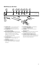
During normal operation with the unit
powered on, the transmitter power level
can be changed by sliding the RF Power
Switch (46) to “H” to increase the
transmitted RF power (for longer range) or
to “L” to decrease the RF power (reduced
range). This is a useful feature as the “L”
setting increases battery life and also
optimizes the number of channels that can
be used simultaneously in a given location.
Use this setting for normal use not requiring
maximum operating range. A range walk
test before use will determine which
setting is best for your application.
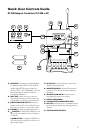
The Power Off/Mute/On Switch (41) has three
positions and functions both as a power
on/off and as an audio mute on/off switch.
After the unit is powered on, slide the
power switch to the “ON” position to un-
mute the audio. With Power Off/Mute/On
switch in either in “MUTE” or ON” position
the receiver’s RF Signal Meter (12) and one
Diversity A or B (8/13) indicator should now
be on, indicating a received signal from the
transmitter. When ready to transmit audio,
slide the power switch to “ON” to un-mute.
To mute, slide the power switch to “MUTE”
again. Adjust the volume of the receiver per
Connecting Audio Outputs section above.
Note: Avoid acoustic feedback (howling or
screeching) by taking care in selecting PA volume,
transmitter location and speaker placement.
The RF Signal meter and the Diversity A/B
indicator on the receiver’s LCD display should
be “On” in normal operation.
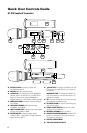
Instrument Use (BT-1KU/GT only)
Secure the connection of the GT
(instrument) cable by lining up the slot
of the 3.5mm mini locking Input Jack (40)
connector and turning the ring to securely
lock in. When ready to play, slide the Power
Off/Mute/On Switch (41) to “ON” position
to un-mute the audio. Adjust the volume
lower on the receiver’s Line Level SUM
Output (18) for one-to-one unity gain with a
hardwired cord or select up to an added
4-5dB boost by leaving the receiver volume
to maximum for normal use with guitars
and bass guitars. Note this function is best
when using two transmitters for switching
during performance as these is only a single
mixed output from the two receivers. If an
individual output per receiver is desired, use
the XLR Mic Outputs (17), noting that those
are only fixed Mic level outputs.
Note: The audio level should be adjusted on
the instrument as when using a hard-wired cord.
For most applications the transmitter’s Input
Volume Level (29) should be set at 0dB for optimal
performance. Use attenuation levels (-10dB, -20dB,
-30dB) only for higher output instruments, such as
bass guitars with active pickups, and then only if
needed for cleaner sound.