


9
from the Volume menu and advance to exit
Setup Mode by pressing the Set button
one more time.
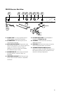
Choose the 2W-1KU operating frequency
by selecting one of ten Groups (9) and one
of 100 Channels (10) that are determined to
be desirable open channels. Press the Set
button to enter the Group setup mode and
the Group icon will flash, then press the
Up/Down button once for single stepping
through the groups, or hold continuously
for faster group selection. Select one of ten
groups available from the Group menu and
then press the Set button again for Channel
Setup mode and the Channel icon will flash,
or press the Set button twice to exit without
changing the channel. In the Channel setup
menu. Press the Up/Down button once
for single stepping through the channels,
or hold continuously for faster channel
selection. Select one of 100 channels
available from the channel menu or press
the Set button twice to skip Volume Level
setting and exit to main menu. During
manual programming, the selected function
will flash for five seconds, or press the Set
button to confirm the selection and the
display will return to the main menu. For
detail how to IR Sync the TX, see IR Sync
Programming in Programming sections of
HT-1KU and BT-1KU transmitter sections.
Rack-mounting the Receiver
The Nady 2W-1KU dual receiver wireless
system includes a rackmount kit for front
antennas mounting. Simply attach the “L”
shape Rack Ears (21) to the unit with the
supplied screws.
Note: Do not mount the receiver on a rack directly
above an amplifier or other source of high heat.
This could degrade the performance of the
2W-1KU. Always ensure adequate airflow and
heat dissipation in any rack configuration.
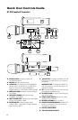
Installing Antennas
Install antennas by connecting the two
Antennas (20) included with your system
onto the two RF Connectors (15) located
on the back of the 2W-1KU receiver. The
two antennas must be installed in order to
the diversity circuit to work properly. The
optimal positions of the antennas are 45°
from the receiver and 90° from each other.
For maximum range, it is always best to
maintain a line-of-sight (no obstructions)
between the receiver antennas and the
transmitter at all times whenever possible.
To install optional Antenna Extension Cables
(22), insert one end of each cable into a rack
ear hole and secure using the removable
nut. Clip the other end of the cable to an
RF Connector (12) on the back of the unit.
Connect the two antennas to the front of
the system.
Powering the Receivers
To power the receivers, plug the supplied
AC/DC Power Supply (19) adapter into
the DC Input Jack (14) on the back of the
receivers, then plug the adapter into an
AC outlet.
Note: Any 16-18VDC power source with 800mA
minimum capacity can also be used.
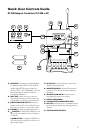
To turn on, press the Power Button (6)
for two seconds. The LCD Display (7) will
light (showing Group, Channel, RF Level
Meter, Diversity, and Output Volume).
The 5-segment AF LED Tree (5) will display
the audio level when the transmitter is on
(audio is transmitted). To turn off, press the
Power button for two seconds. The LCD will
display “OFF” then the backlight will turn
off indicating the receivers are off.
Connect either the ¼” Unbalanced SUM Line
Out (18) or each XLR Balanced Mic Outs (17)
to your mixing board, effect, or amplifier
inputs (See Connecting the Audio Outputs
section).