7
Controls & Connections
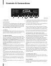
2. MAIN CONTROL SECTION
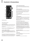
(13) PHANTOM POWER
When this switch is depressed, +48V of phantom power will be
supplied to the XLR mic inputs to power condenser microphones.
The phantom power LED will illuminate when the switch is
depressed to ON.
[Note: When turning on the Phantom Power(13) turn the Main
Level fader to minimum to avoid audible transient noise].
(14) DUAL CHANNEL LED METER
This dual 4-stage stereo output LED VU meter will display the
relative output level of the Left and Right Main output or the 1/8”
mini stereo input if the Tape/USB to Control Room(19) switch is
enabled.
The top red Peak LED will light when the output signal is just
below clipping. It is acceptable if the red LED lights occasionally. If
the red LED lights more than occasionally, you should turn down
the corresponding volume control to avoid audible distortion.
(15) MAIN TO REC/USB OUT SWITCH
This switch enables the Main left and right signals to be sent
to the
1
⁄8” mini output, rear panel Record Outputs, and the USB
output.
(16) AUX TO REC SWITCH
This switch enables the channel Aux Send signals to be sent
to the
1
⁄8” mini output, rear panel Record Outputs, and the USB
output. Both the Main left and right signals and the Aux Send
signals can be simultaneously sent to these outputs if both
switches (15 & 16) are enabled.
(17) AUX RETURN LEVEL
This adjusts the level from the Aux Return(24) that is sent to the
Main Mix.
(18) TAPE/USB TO MIX
Enabling this switch actually mixes a set of inputs onto the main
bus. Depressing this pushbutton switch will send the rear panel
Tape Inputs(31), USB Input(32), and Stereo Mini Input(25)
signals to the Main mix which can then be adjusted by the Main
Level(21) fader control.
(19) TAPE/USB TO CONTROL SWITCH
This switch will toggle between monitoring the Main mix and
a set of other inputs. When the switch is disabled (button
out), the Main mix signals are sent to the Control Room and
Headphone outputs. Enabling the switch (button depressed)
will send the rear panel Tape Inputs(31), USB Input(32), and
Stereo Mini Input(25) signals exclusively to the Control Room
and Headphone outputs. Either signals can then be adjusted by
the Control Room Level(20) control. Also, when this switch is
enabled, the Dual Channel LED Meter(14) will indicate the signal
levels of the rear panel Tape Inputs, USB Input, and Stereo Mini
Input signals and not the Main mix.
(20) CONTROL ROOM LEVEL
This adjusts the level of the Control Room and the Headphones
outputs.
(21) MAIN LEVEL
This fader control adjusts the final level of the main stereo signal
that is sent to Main Outputs(21).
(22) POWER LED
The LED will illuminate when the unit is switched on.
Main Control Section
13
15
16
17
22
14
21
18
19
20


