


8
Controls & Connections
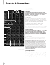
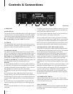
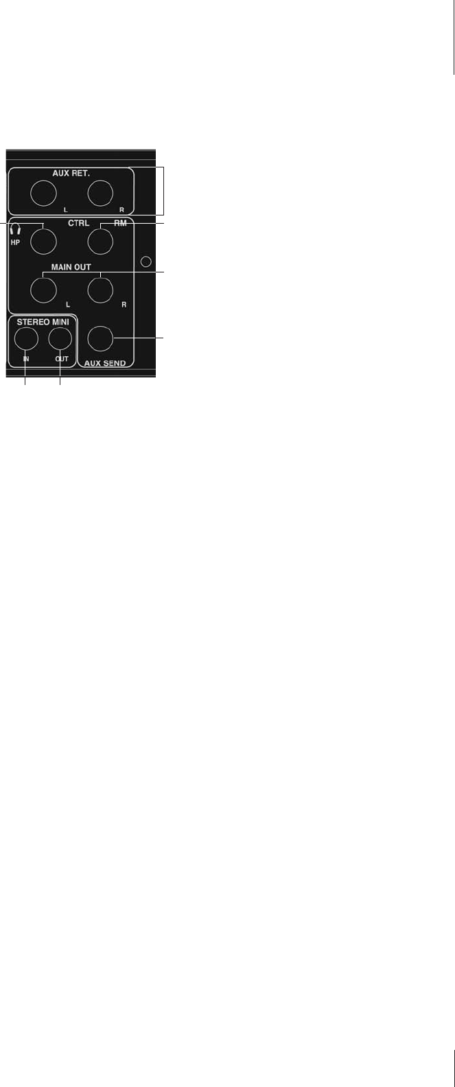
3. MASTER INPUT / OUTPUT SECTION
(23) AUX SEND
The Aux Send jack provides a mono mixed signal from the input
channels, which can be connected to an external effects unit or
other devices. The signal is adjusted by the channel Aux Send(7)
controls of each channel and is post channel level control.
(24) AUX RETURN
These balanced Left and Right Aux ¼” inputs can be used to
return the effected signal into the MM-15USB or it can be used
as an auxiliary input for line level devices. The signal level is
adjusted by the Aux Return(17) control.
(25) STEREO MINI INPUT
This 1/8” stereo mini input can be used to input stereo audio
signals from any piece of equipment with line level or headphone
level outputs, in particular cassette, CD, or MP3 players. The
Tape/USB To Mix(18) pushbutton switch must be enabled for the
1/8” input signal to be mixed onto the Main bus.
(26) STEREO MINI OUTPUT
This 1/8” TRS jack outputs a line level stereo signal. When the
Aux to Record(16) switch is enabled, the Channel Aux bus
signal is sent to both L and R connections on the TRS jack. When
the Main to Rec/USB(15) switch is enabled the
1
⁄8” output signal
is post Main fader and true stereo L/R. Both Aux and Main signals
can be output simultaneously. When both switches are disabled,
there is no output at the
1
⁄8” output.
(27) MAIN OUTPUTS
These unbalanced
1
⁄4” jacks output the final Main Mix Left and
Right line level signals.
(28) HEADPHONES
The Headphones
1
⁄4” stereo output can be used to monitor either
the Main mix or a set of other inputs depending on the position of
the Tape/USB to Control(19) switch.
The headphone jack will power headphones with impedances
of 8
^
or greater. The Control Room output jack must be left
unplugged while headphones are being used. Inserting a plug
into the Control Room (29) output automatically configures the
unit for Control Room mode, thereby disabling the headphone
Right signal and allowing the Headphones jack to be used as a
Control Room Left output.
(29) CONTROL ROOM
Inserting a plug into the Control Room right
1
⁄4” jack automatically
configures the unit for Control Room mode. This
1
⁄4” TS jack will
output the Right signal. The Headphones(28)
1
⁄4” TS jack will out-
put the Left line level signal. These L-R outputs can be connected
to an amp used to power stereo control room monitor speakers,
or used for any output application.
24
29
27
23
25 26
28
Master Input/Output Section