9
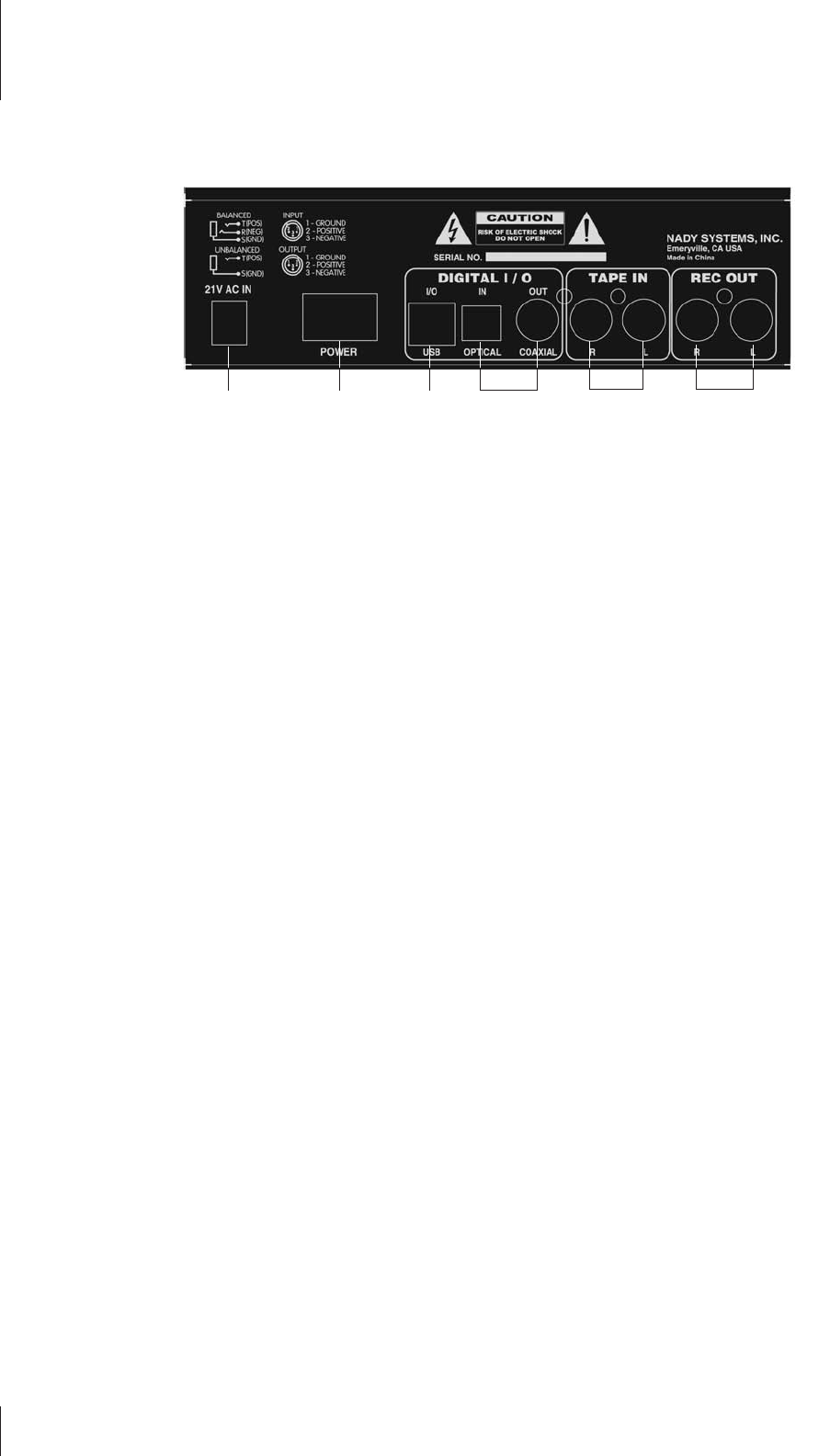
4. REAR PANEL
(30) RECORD OUT
The Record Out Left and Right RCA jacks provide signal output to
recording devices, home audio equipment, or external amplifiers.
These outputs take the signal from the Main bus, the Aux Send
bus, or a combination of both depending on the positions of the
Main To Rec/USB(15) and Aux To Rec(16) switches.
(31) TAPE IN
The Left and Right Tape Input RCA jacks allow stereo receivers,
cassette recorders, CD players, or any external equipment, to be
added to the Main mix outputs pre-Main Level control.
(32) USB INPUT/OUTPUT
The USB I/O can be connected directly to any computer with a
USB 1.0 (or higher) port for easy plug-and-play operation using a
standard “A-B” USB cable. For playback, make sure the Tape/
USB To Mix(18) and Tape/USB To Control(19) switches are set
appropriately for desired signal routing. For recording, Make sure
the Main To Rec/USB Out(15) and Aux To Rec(16) switches are
set appropriately to select your desired signal source.
Windows
1. Connect the MM-15USB to the computer using a standard “A-
B” USB cable. Your computer may automatically set up the MM-
15USB as its Playback and Recording Device. If not, to set your
MM-15USB as such a device, open the control panel.
2. Access Sounds and Audio Devices through the Setting>Control
Panel.
3. In the Audio tab, select “USB Audio Device” as the Sound
Playback device if you want to send audio from the computer to
the MM-15USB. For sending audio from the MM-15USB into the
computer, select “USB Audio Device” as the Sound Recording
device.
4. Your audio player or recording software may also input and
output configurations that need to be to the “USB Audio Device”
Mac OS
1. Connect the MM-15USB to your Mac using a standard “A-B”
USB cable.
2. Configure your DAW software to select the mixer as your input
or output device. This can usually be done in your Hardware Op-
tions by selecting “USB Audio Device”.
3. Or, you can select “USB Audio Device” as your input device in
your Sound options under System Preferences.
You may experience a delay in hearing your audio if monitoring
in real time. Such a slight delay is called “latency” and is common
for many types of software used with this unit. If real time coinci-
dence of the input and amplified signal heard though the comput-
er monitors is required then certain software may be necessary.
(33) S/PDIF OPTICAL INPUT AND COAXIAL OUTPUT
The S/PDIF I/O exclusively provides a direct digital link between
the USB interface and compatible S/PDIF devices. This facilitates
a direct digital transfer at sample rates of up to 48kHz.
The digital optical input receives S/PDIF digital input through a
TOSLINK cable. Digital input is automatically selected when a
proper input signal is detected. The digital input will automatically
override the audio from the mixer section to the USB output.
The digital coaxial output transmits S/PDIF digital output to com-
patible devices. The coaxial connection requires 75 ohm coaxial
cable.
Note also that optical input will not be converted to analog, nor will
analog be converted to digital coax. The top panel selector but-
tons have no effect on this operation. Also, this interface does not
require the mixer to be on. USB power is all that is needed.
When transmission is first initiated, or if it is interrupted, it may
be necessary to restart software applications and/or unplug and
reconnect USB cable.
(34) POWER ON/OFF SWITCH
Use this rocker switch to turn the unit on and off. [Note: When
operating the power switch, turn the Main Level fader to minimum
to avoid audible transient noise].
(35) AC IN SOCKET
Connect the corresponding plug of the supplied external AC pow-
er adapter to this socket before plugging the AC power adapter
into a wall outlet.
303133323435 Rear Panel
Controls & Connections
