


10
2.4 Das schaltbare Hochpaßfilter,
der –10 dB-Schalter
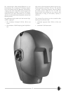
Nach dem Öffnen des Kunstkopfes (s. Kapitel 2.3)
werden an der Oberseite der Ausgangsstufe zwei
Kippschalter zugänglich:
Links der 3-stufige Schalter für verschiedene Grenz-
frequenzen eines Hochpaßfilters, rechts der –10 dB-
Schalter zur Reduzierung des Übertragungsmaßes.
Beide Schalter wirken jeweils auf beide Kanäle.
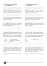
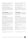
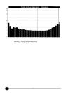
Die –3 dB-Grenzfrequenzen des Hochpaßfilters sind:
8 Hz in Schalterstellung LIN, 40 Hz und 150 Hz. Da-
durch lassen sich tieffrequente Störungen wie z.B.
Körperschall ausblenden.
2.5 Mikrophonkabel
Der symmetrische Anschluß des Kunstkopfes
KU 100 erfolgt über das beigelegte 5-polige ge-
schirmte Mikrophonkabel IC 5.
Mit Hilfe des ebenfalls zum Lieferumfang gehören-
den Adapterkabels AC 20 kann die 5-polige XLR-
Armatur auf zwei 3-polige XLR-Stecker aufgelöst
werden und paßt dann auf in der Studiotechnik üb-
liche (phantomgespeiste) Mikrophoneingänge.
Die Kabelfarbe gelb des Adapterkabels AC 20 be-
zeichnet den linken Kanal, die Farbe rot den rechten
Kanal.
Die 3-poligen Stecker XLR 3 M sind entsprechend
DIN EN 60268-12 bzw. IEC 60268-12 beschaltet:
Jeweils
Stift 1: 0 V, Gehäuse (Masse)
Stift 2 (+): Modulation für symmetrische
Stift 3: Eingänge
Als separates Zubehör ist das Adapterkabel AC 29
lieferbar. Mit ihm kann der 5-polige XLR-Stecker des
Kunstkopfes auf unsymmetrische Eingänge von z.B.
DAT-Recordern adaptiert werden.
Das Kabel AC 29 führt die Modulation auf zwei
6,3 mm Ø Monoklinkenstecker. Das Kabel hat RC-
Glieder eingebaut, um die am 5-poligen XLR-Aus-
gang des KU 100 anstehende Gleichspannung abzu-
blocken.
(+) positiver Spannungsanstieg bei einem Schalldruckanstieg vor dem jewei-
ligen Ohr
2.4 Switchable High-Pass Filter,
–10 dB Switch
After opening the dummy head, (see chapter 2.3)
two flip switches are accessible on top of the out-
put stage:
On the left-hand side is a 3-position switch for
different corner frequencies of a high-pass filter. The
–10 dB pad switch is on the right.
Each switch influences both channels.
The –3 dB corner frequencies of the high-pass filter
are:
8 Hz in the LIN position, 40 Hz, and 150 Hz. This
feature permits elimination of low-frequency inter-
ferences, such as structure-borne noise.
2.5 Microphone Cable
Balanced connection to the KU 100 dummy head is
possible via the shielded, 5-conductor microphone
cable IC 5 (supplied).
The 5-pin XLR fitting can be distributed to two
3-pin XLR connectors by means of the AC 20
adapter cable (supplied) and then matches the com-
mon (phantom-powered) microphone inputs for
studio applications.
The yellow cable of the AC 20 adapter cable is for
the left channel, the red cable for the right channel.
The 3-pin XLR 3 male connectors are wired accord-
ing to DIN EN 60268-12 and/or IEC 60268-12:
Pin 1: 0 V, shield (ground)
Pin 2 (+):
modulation for balanced inputs
Pin 3:
The AC 29 adapter cable is available as separate ac-
cessory. It facilitates connection of the 5-pin XLR
connector of the dummy head to unbalanced inputs,
e.g. of DAT recoders.
The AC 29 cable routes the modulation to two
mono 1/4" type jack-plug connectors, 6.3 mm. The
cable is provided with integrated RC elements in or-
der to ward off the dc voltage which is available at
the 5-pin XLR output of the KU 100.
(+) polarity at a sudden rise of sound pressure in front of the respective
ear