


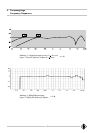

17
Da beide Ohradapter im Werk auf gleiche Über-
tragungsmaße ausgesucht werden, ist darüberhinaus
zu empfehlen, bei einem Defekt jeweils beide Ohr-
adapter einzuschicken.
Anstelle der Ohradapter läßt sich der Meßadapter
MA 84/KU 100 auf die Gehäuserohre schrauben.
Dann kann in den Meßadapter eine Modulations-
spannung eingespeist und das gesamte System elek-
trisch überprüft werden, ohne einen akustischen
Meßraum zu benötigen.
Beim Zusammensetzen der Teile ist darauf zu
achten, daß
• die Kontaktstifte der Mikrophonkapseln korrekt in
den jeweiligen Gabelkontakt an den Stirnseiten
der Platine eingeführt werden,
• die richtigen Außenohren entsprechend der
Gravur L, R (für links und rechts) auf dem
Mittelteil auf die Ohradapter aufgeschnappt
werden,
• das Zuführungskabel im Stauraum unter dem
zylindrischen Gehäuse verstaut wird und dafür der
Kabelaustritt aus dem Vierkant-Mittelteil nach
unten unten
unten unten
unten in den Stauraum zeigt,
• das Anschlußkabel zur Batteriehalterung
oberhalboberhalb
oberhalboberhalb
oberhalb
des zylindrischen Gehäuses verläuft, damit der
Batteriesatz bequem herausgenommen werden
kann.
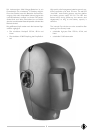
Die Ohradapter sind für das linke und für das rechte
Ohr identisch, sind also keinem Ohr besonders
zugeordnet.
Das viereckige Gehäuse der Ausgangsstufe kann aus
dem Vorderkopf herausgenommen werden, wenn
die beiden Befestigungsschrauben entfernt worden
sind.
Um das Gehäuse zu öffnen, muß erst die obere
Platte abgeschraubt und herausgehoben werden.
Anschließend kann die untere Platte mit den Steck-
verbindern etc. abgeschraubt und mitsamt dem kom-
pletten Innenaufbau vorsichtig herausgezogen werden.
Wenn die Ohren und die Ohradapter vom Ohr-
system abgenommen sind, kann dieses durch das
Gehäuse der Ausgangsstufe hindurchgeschoben
werden. Es können aber auch die Anschlußleitungen
zum Ohrsystem von der Ausgangsstufe abgezogen
werden, wenn zuvor die Schelle zu deren Zug-
entlastung von der Platine abgeschraubt worden ist.
Both ear adapters are carefully matched by the
manufacturer in all relevant characteristics. Therefore
both ear adapters should be returned to the factory
whenever any repair work is necessary.
The ear adapters can be replaced by the MA 84/
KU 100 test adapter. lt is then possible to feed a
modulation voltage into the test adapter, so that the
entire system can be checked electrically without the
need to use an acoustic measuring room.
When assembling the parts, please ensure that:
• the contact pins of the microphone capsules are
properly inserted into the respective forked
contact at the face of the board,
• the proper outer ears are snapped onto the ear
adapters as indicated by the marks L (left) and
R (right) on the central part,
• the incoming cable is stored in the cable space
below the cylindrical enclosure, with the cable
outlet of the central square pointing
downwardsdownwards
downwardsdownwards
downwards
to the cable space,
• the connecting cable leading to the battery
holder runs
above above
above above
above the cylindrical enclosure, so
that the batteries can be removed without any
problems.
Note: The ear adapters are identical for the left and
right ears, i.e. not assigned to a particular ear.
The square enclosure of the output stage can be re-
moved from the front portion of the head after the
two fixing screws have been removed.
In order to open the enclosure, first remove the
screws of the upper board (rear panel) and detach
it. Thereafter, the lower board (front panel) includ-
ing the plug connectors etc. can be unscrewed and
pulled out carefully, together with the complete
internal components.
After the ears and the ear adapters have been re-
moved from the ear system, it can be pushed
through the enclosure of the output stage. lt is, how-
ever, also possible to pull the connecting cables lead-
ing to the ear system off the output stage, if the ten-
sion relief clamp for the connecting cables has been
taken off the board beforehand.