


2
3
Inhaltsverzeichnis
1. Kurzbeschreibung
2. Das Kondensatormikrophon M 150 Tube
2.1 Einige Zusatzinformationen zur Schaltungs-
technik im M 150 Tube
2.2 Inbetriebnahme
2.3 Ausführungsform und Beschaltung des
Mikrophon- und Netzgeräteausgangs
2.4 Mikrophonkabel
3. Netzgerät
3.1 Betrieb an unsymmetrischen Eingängen
4. Technische Daten
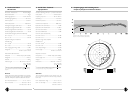
5. Frequenzgänge und Polardiagramme
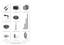
6. Zubehör
1. Kurzbeschreibung
Das Kondensatormikrophon M 150 Tube ist ein Stu-
diomikrophon mit der Richtcharakteristik Kugel.
Als Eingangsstufe wird eine Röhre verwendet, um
deren charakteristische Klangeigenschaften zu nutzen.
Das M 150 Tube zeichnet sich aus durch
• besonders niedriges Eigengeräusch und hohe
Aussteuerbarkeit,
• ein neu entwickeltes Schaltungskonzept mit einer
Röhre als Eingangsstufe und transformatorlosem
Ausgang,
• den vollen, reichen und warmen Klang des Röh-
renmikrophons.
Auf der Rückseite befinden sich
• ein schaltbarer Hochpaß, Grenzfrequenz (–3 dB)
ca. 16 Hz (LIN) oder 40 Hz,
• ein 10 dB-Dämpfungsschalter.
Das Mikrophon hat einen symmetrischen, übertrager-
losen Ausgang und wird aus dem zugehörigen Netz-
gerät N 149 A oder N 149 V gespeist.
Die Einsprechrichtung des M 150 Tube wird durch
das Neumann-Emblem gekennzeichnet.
Table of Contents
1. Description
2. The M 150 Tube
Condenser Microphone
2.1 Additional Information on the
M 150 Tube
Circuit Design
2.2 Getting Started
2.3 Type and Configuration of the Microphone and
Power Supply Outputs
2.4 Microphone Cables
3. Power Supply Unit
3.1 Operation with Unbalanced Inputs
4. Technical Specifications
5. Frequency Responses and Polar Pattern
6. Accessories
1. Description
The M 150 Tube is a studio condenser microphone
with a capsule with omnidirectional polar pattern.
The input stage is a vacuum tube (valve) with the
sound properties unique to this type of device.
The M 150 Tube is characterized by
• very low inherent self-noise and a wide dynamic
range
• a newly developed circuit design with a vacuum
tube input stage and a transformerless output
stage
• the full, rich and warm sound of a tube micro-
phone.
At the rear of the microphone may be found
• a switchable high-pass, –3 dB point at 16 Hz ap-
prox. in LIN position, or 40 Hz,
• a 10 dB attenuation switch.
The microphone has a balanced transformerless out-
put and is powered by the
N 149 A or N 149 V
power supply unit.
The front of the M 150 Tube microphone is desig-
nated by the Neumann logo.
2. Das Kondensatormikrophon
M 150 Tube
Das Kondensatormikrophon M 150 Tube ist ein
transformatorloses Röhren-Mikrophon, das insbeson-
dere als Stereo- oder Mehrkanal-Hauptmikrophon
seinen Einsatz findet (z.B. „Decca-Tree“).
Sein Name ist eine Reminiszenz an das früher von
Neumann gebaute Röhrenmikrophon M 50, in dem
die gleiche besondere Kapselkonstruktion verwendet
worden war. Im Gegensatz zu Druckmikrophonen
üblicher, d.h. zylindrischer, Bauweise ist beim
M 150 Tube der Wandler bündig in die Oberfläche
einer Kugel mit 40 mm Durchmesser eingebaut. So
werden die speziellen akustischen Druckstau- und
Beugungsverhältnisse einer Kugel ausgenutzt:
Dies sind z.B. ein besonders sanfter Anstieg in den
Druckstaubereich sowie ein mit steigender Frequenz
sehr gleichmäßiger Anstieg des Bündelungsmaßes.
Infolge des Kugeldurchmessers beginnt der Druck-
stau vor der Membran bei frontalem Schalleinfall be-
reits bei ca. 1000 Hz, erreicht aber für hohe Fre-
quenzen nur Werte von maximal 6 dB. Dagegen
kann der Druckanstieg bei zylindrischen Druckemp-
fängern 10 dB betragen.
Auch die Variation des Schalldruckpegels in Abhän-
gigkeit vom Schalleinfallswinkel ist bei zylindrischen
Körpern größer (bis 20 dB) als bei einer Kugel (bis
15 dB). So besitzt das M 150 Tube im oberen Fre-
quenzbereich ausgeglichenere, fast einem Druckgra-
dientenmikrophon vergleichbare Richteigenschaften,
bietet aber als Druckempfänger ein bis zu tiefsten
Frequenzen lineares Übertragungsmaß.
Die Metallmembran der Druckkapsel hat einen
Durchmesser von nur 12 mm und ist extrem dünn.
Dadurch wird ein besonders schnelles Einschwing-
verhalten erreicht.
Auf der Rückseite des Mikrophons befindet sich ein
–10 dB-Schalter und ein schaltbares Trittschallfilter
zum Absenken von Frequenzen unterhalb 40 Hz. In
Stellung „LIN“ verbleibt eine Grenzfrequenz von
16 Hz. Dadurch sollen im wesentlichen dem Mikro-
phon nachgeschaltete Geräte vor unterhörfrequentem
Schall (z.B. starke Luftströmungen) geschützt werden.
Die –10 dB-Funktion wird durch Spannungsteilung
erreicht und sollte nur verwendet werden, wenn bei
sehr hohen Signalpegeln für nachfolgende Geräte die
Gefahr der Übersteuerung besteht. Der Schalter er-
weitert nicht den Dynamikumfang des Mikrophons,
sondern verschiebt den Ausgangspegel um 10 dB
nach unten.
2. The M 150 Tube Condenser
Microphone
The M 150 Tube is a transformerless tube micro-
phone. It is especially suited as main microphone for
stereo and multichannel recording (e.g. “Decca
Tree”).
It's name refers back to a former Neumann tube mi-
crophone M 50 which the same special capsule de-
sign was incorporated. In contrast to pressure micro-
phones of conventional, i.e. cylindrical construction,
the transducer of the M 150 Tube is built flush into
the surface of a sphere 40 mm in diameter. In this
way, the special acoustic pressure build-up and dif-
fraction relationships of a sphere are exploited:
For example, a particularly smooth rise in the pres-
sure build-up range and a very even increase in the
directivity index with rising frequency. Resulting from
the diameter of the sphere, the pressure build-up
begins in front of the diaphragm with frontal sound
impingement already at some 1000 Hz, but attains
values of only 6 dB at the most for high frequencies.
In comparison, the pressure rise may amount to
some 10 dB with cylindrical pressure microphones.
In addition, the variation in the sound pressure lev-
el in dependance of sound incidence is greater with
cylindrical bodies (up to 20 dB) than it is with a
sphere (up to 15 dB). Thus, in the upper frequency
range, the M 150 Tube possesses a more evenly
balanced directional characteristic which is almost
comparable with a pressure gradient microphone,
while at the same time offering as a pressure micro-
phone a bass response which is linear all the way
down to the lowest frequencies.
The metal diaphragm of the pressure capsule has a
diameter of only 12 mm and is extremely thin. The
result is seen in a remarkably fast transient behaviour.
At the rear of the microphone is a –10 dB switch
and a switchable footfall filter for the attenuation of
frequencies below 40 Hz. In the position “LIN”, a
limit frequency of 16 Hz is made active. This is main-
ly to protect the console inputs from the effects of
sub-audio noise (e.g. strong air currents).
The –10 dB function is effected by voltage division
and should be used only where the danger of over-
loading follow-on equipment with very high signal lev-
els is present. This switch does not extend the dy-
namic range of the microphone, but shifts the output
level down by 10 dB.