


6
7
Wird eine externe Phantomspeisung an- oder abge-
schaltet, ergibt sich kurzzeitig ein leicht erhöhter Ei-
gengeräuschpegel.
Der Schalter des N 149 A bzw. N 149 V unterbricht
die Zuleitungen des eingebauten Netzteiles sekun-
därseitig. Zur Stromersparnis sollte das N 149 A/
N 149 V bei längerer Nichtbenutzung vom Strom-
netz getrennt werden.
Das M 150 Tube darf nur mit den Neumann-
Speisegeräten N 149, N 149 A oder N 149 V be-
trieben werden.
Das M 150 Tube ist als Druckempfänger sehr un-
empfindlich gegen Wind- und Popstörungen. Für Ge-
sangsanwendungen kann gegebenenfalls ein Pop-
schutz verwendet werden.
2.3 Ausführungsform und Beschaltung des
Mikrophon- und Netzgeräteausgangs
Das Mikrophon hat eine nickelmatte Oberfläche. Der
8-polige Stecker des Mikrophons und des Netzgerä-
tes ist folgendermaßen beschaltet:
Pin 1: –70 V
Pin 2: +5 V
Pin 3: Modulation, +Phase
Pin 4: +70 V
Pin 5: Sensorleitung
Pin 6: Masse
Pin 7: +32 V
Pin 8: Modulation, –Phase
Das zum Lieferumfang gehörende 8-polige Kabel ver-
bindet das Mikrophon mit dem Netzgerät.
Die Modulation liegt hier an einem 3-poligen
XLR-Stecker. Erforderliches Gegenstück: XLR 3F. Die
Zuordnung der Mikrophonanschlüsse entspricht
DIN 45 599, Kennzeichen „I“ bzw. IEC 268-12 (pin.
conn. 130-x-IEC 02).
Bei einem Schalldruckanstieg vor der Mikrophon-
membran tritt an Stift 2 eine positive Spannung auf.
2.4 Mikrophonkabel
Für das M 150 Tube stehen folgende Kabel zur Ver-
fügung (siehe Kap. 6 „Zubehör“):
KT 8KT 8
KT 8KT 8
KT 8 ........................................ sw .............................Best.-Nr. 08407
(gehört zum Lieferumfang)
IC 3 mtIC 3 mt
IC 3 mtIC 3 mt
IC 3 mt ................................. sw .............................Best.-Nr. 06543
ternal phantom power source is switched on or off,
only a short, slight rise in the residual noise level will
result.
The on/off switch of the power supply functions as
a secondary voltage interrupt for the feeds from the
built-in mains unit. To save energy, the N 149 A/
N 149 V should be unplugged from the wall outlet
if it is not in operation for an extended period.
The M 150 Tube must only be operated with the
Neumann power supplies N 149, N 149 A or
N 149 V.
Being a pressure transducer the M 150 Tube is very
insensitive to wind and pop noise. If necessary a pop
screen can be used for recording vocals.
2.3 Type and Configuration of the
Microphone and Power Supply Outputs
The microphone is finished in matt nickel. The 8-pin
connector of the microphone and the corresponding
connector of the power supply unit have the follow-
ing configuration:
Pin 1: –70 V
Pin 2: +5 V
Pin 3: audio signal, +phase
Pin 4: +70 V
Pin 5: sensor line
Pin 6: ground
Pin 7: +32 V
Pin 8: audio signal, –phase
The included eight-core cable connects the micro-
phone to the power supply unit.
At the power supply unit, the audio signal is availa-
ble at a 3-pin XLR socket which requires an XLR-
3F connector. The pin assignment corresponds to
DIN 45 599, part “I” and IEC 268-12 (pin. conn.
130-x-IEC 02), respectively.
An increase in sound pressure at the microphone‘s
diaphragm produces a positive voltage at pin 2.
2.4 Microphone Cables
The following cables are available for the
M 150 Tube (see the topic “Accessories”):
KT 8KT 8
KT 8KT 8
KT 8 ........................................ blk.............................. Cat. No. 08407
(included in the supply schedule)
IC 3 mtIC 3 mt
IC 3 mtIC 3 mt
IC 3 mt ................................. blk.............................. Cat. No. 06543
Das Mikrophon ist besonders unempfindlich gegen
kapazitive Belastung. TIM- und Frequenzgangverzer-
rungen werden auch bei Verwendung sehr langer
Kabel nicht hervorgerufen. Daher sind für die Modu-
lation Kabellängen bis etwa 300 m erlaubt. Das
8-polige Kabel zwischen Mikrophon und Netzgerät
darf dabei bis etwa 100 m lang sein.
3. Netzgerät
Das Universal-Netzgerät N 149 A kann in folgenden
Ausführungsformen geliefert werden:
NN
NN
N
149149
149149
149
A EuroA Euro
A EuroA Euro
A Euro ................. sw .............................Best.-Nr. 08447
NN
NN
N
149149
149149
149
A USA US
A USA US
A US ...................... sw .............................Best.-Nr. 08446
N 149 A UKN 149 A UK
N 149 A UKN 149 A UK
N 149 A UK ..................... sw .............................Best.-Nr. 08448
Die unterschiedlichen Versionen der Netzgeräte un-
terscheiden sich lediglich durch ihre Netzkabel.
Das Vintage-Netzgerät N 149 V kann in folgenden
Ausführungsformen geliefert werden:
N 149 V EuroN 149 V Euro
N 149 V EuroN 149 V Euro
N 149 V Euro ....................................... Best.-Nr. 12253.00101
N 149 V USN 149 V US
N 149 V USN 149 V US
N 149 V US............................................ Best.-Nr. 12253.00201
N 149 V UKN 149 V UK
N 149 V UKN 149 V UK
N 149 V UK........................................... Best.-Nr. 12253.00301
Die unterschiedlichen Versionen der Netzgeräte un-
terscheiden sich lediglich durch ihre Netzkabel.
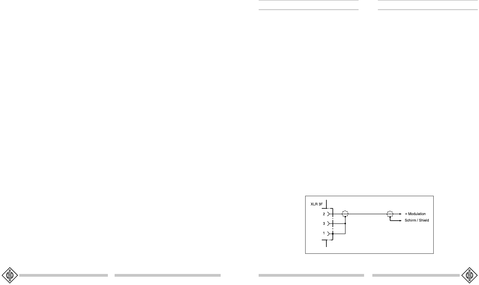
3.1 Betrieb an unsymmetrischen Eingängen
Die Netzgeräte N 149 A und N 149 V haben einen
symmetrischen, gleichspannungsfreien Ausgang. Die
Zuordnung der Mikrophonanschlüsse entspricht
DIN 45 599, Kennzeichen „I“ bzw. IEC 268-12 (pin.
conn. 130-X-IEC 02):
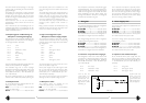
Pin 1: 0 V, Masse
Pin 2: Modulation, +Phase
Pin 3: Modulation, –Phase
Pin 2 ist also die
„heiße Phase“, und
Pin 3 muß für un-
symmetrische Ein-
gänge an Masse ge-
legt werden (siehe
Abbildung 1).
The M 150 Tube microphone is especially insensi-
tive to capacitive loads. Even the use of long cables
does not cause TIM or frequency response distor-
tions. Thus, the audio signal cable can have a length
of up to approx. 300 m, the 8-core connecting ca-
ble between the microphone and the power supply
unit can be as long as approx. 100 m.
3. Power Supply Unit
The N 149 A power supply unit is available in the fol-
lowing versions:
N 149 A EuroN 149 A Euro
N 149 A EuroN 149 A Euro
N 149 A Euro ................. blk.............................. Cat. No. 08447
N 149 A USN 149 A US
N 149 A USN 149 A US
N 149 A US ...................... blk ..............................Cat. No. 08446
N 149 A UKN 149 A UK
N 149 A UKN 149 A UK
N 149 A UK ..................... blk..............................Cat. No. 08448
The three available versions of the N 149 A just dif-
fer in their enclosed mains power cable.
The N 149 V vintage power supply unit is available
in the following versions:
N 149 V EuroN 149 V Euro
N 149 V EuroN 149 V Euro
N 149 V Euro ........................................ Cat. No. 12253.00101
N 149 V USN 149 V US
N 149 V USN 149 V US
N 149 V US ............................................. Cat. No. 12253.00201
N 149 V UKN 149 V UK
N 149 V UKN 149 V UK
N 149 V UK............................................ Cat. No. 12253.00301
The three available versions of the N 149 V just dif-
fer in their enclosed mains power cable.
3.1 Operation with Unbalanced Inputs
At the N 149 A/N 149 V power supply units, the
audio signal is available at a balanced XLR-3 output.
The pin assignment corresponds to DIN 45 599, part
“I” and IEC 268-12 (pin. conn. 130-x-IEC 02), re-
spectively:
Pin 1: 0 V, ground
Pin 2: audio signal, +phase
Pin 3: audio signal, –phase
So pin 2 is the “hot
phase”, pin 3 must
be connected to
ground when used
with unbalanced in-
puts (see figure 1).
Abb. 1 / Fig. 1