


OnSite Expansion Modules Quick Start Guide 3
2.2 Cable Management
The HD-E1 module uses a future bus connector on the front panel and requires the use of cables with compatible
plugs for access to the E1 signals. These cables are ordered separately from the module and need to be specified
according to the termination option for the module (75-ohm or 120-ohm) and the required cable length for the
site.
Note Contact your local Patton sales representative if the shipment does not include the required cables for
the module.
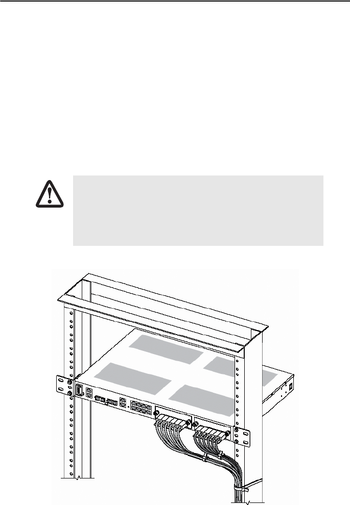
Chapter 7 of the OnSite Series Administrator’s Reference Guide provides information on the location and signal
pin-out for each of the 21 E1 ports on the future bus connector. Each module requires six cables for access to all
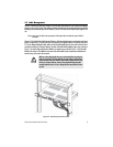
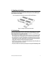
21 E1 ports. When installing the cables, make sure that the cable bundle does not cause strain on the future bus
connector by pulling it up or down or sideways. You may tie the cable bundle together using a strap, as shown in
Figure 2, to create a strain relief bend. In addition, use another strap, as shown in Figure 2, to tie the cable
bundle to the rack post. This additional strap secures the cable bundle in place and prevents accidental move-
ment that may cause strain to the connector.
Figure 2. Cable dressing for the HD-E1 module
Make sure that cable plug has the correct orientation before inserting the
plug into the module. The plug should be inserted within a single section
of the future bus connector with the release latch facing down. (The mod-
ule has six, 24-pin connector sections.) The plug should snap into place
smoothly without the use of force. Wrong insertion may bend the connec-
tor pins.
CAUTION