


OnSite Expansion Modules Quick Start Guide 7
5.1 Unpacking and Installation
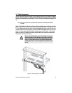
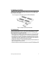
To install the 2-port STM-1 module, follow the procedures in Chapter 10 of the OnSite Series Administrator’s Ref-
erence Guide. Figure 1 shows the alignment and insertion of the module into one of the available expansion
slots of a modular OS-10 Series platform.
Note Hot swapping the 2-port STM-1 module is supported on the OS1052 and OS1063 platforms.
Figure 5. Installing the 2-port STM-1 optical interface module
5.2 Getting Started
The 2-port STM-1 module supports insertion into or removal from any available expansion slot on the modular
OS1052 and OS1063 chassis while the system is powered on and carrying traffic. The following procedure
applies to module insertion into a system that is powered ON:
•
After the module is securely installed to the chassis (using the mounted screws on the front panel), the STAT
LED of the module becomes a solid amber light for about ten seconds after the system detects the module.
•
After the STAT LED turns off, use the OS-10 Node Manager to set the Administrative Type for the slot where
the module resides to 2-port STM-1o expansion module or 2-port STM-1e expansion module, depending on
the type of STM-1 module that you install into the system (optical or electrical).
•
The STAT LED of the module becomes a solid green light when the Administrative Status of the module is set to
Enabled and the Operational Status is in service (IS).
•
At this point, the module is now ready for the provisioning of services using the OS-10 Node Manager or EMS.