


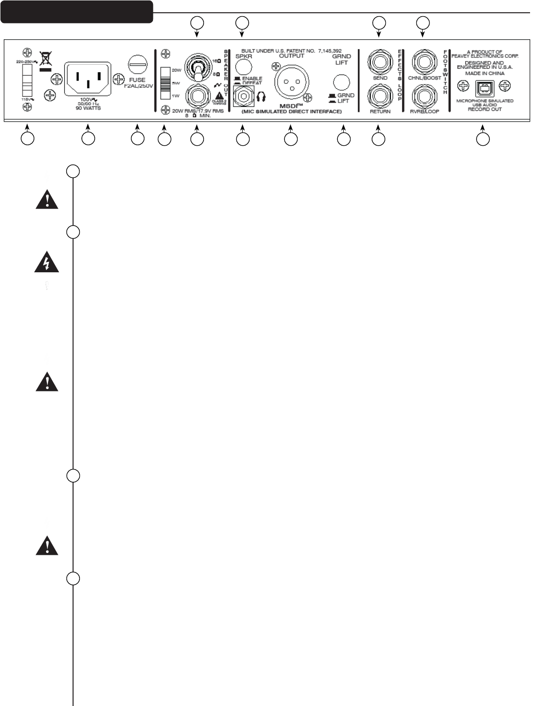
VOLTAGE SELECTOR SWITCH
This selects between two different AC line/mains voltages. This should not normally be adjusted by the
user, hence the clear plastic shield. This should already be set to the correct line/mains voltage in your
country/territory.
AC POWER INLET:
This is the receptacle for an IEC line cord, which provides AC power to the unit. Connect the line cord
to this connector to provide power to the unit. Damage to the equipment may result if improper line
voltage is used. (See VOLTAGE SELECTOR SWITCH #15).
Never break off the ground pin on any equipment. It is provided for your safety. If the outlet used does
not have a ground pin, a suitable grounding adapter should be used and the third wire should be
grounded properly. To prevent the risk of shock or fire hazard, always make sure that the amplifier and all
associated equipment is properly grounded.
Note for UK ONLY
As the colors of the wires in the mains lead of this apparatus may not correspond with the colored
markings identifying the terminals in your plug, proceed as follows: (1) The wire that is colored green
and yellow must be connected to the terminal that is marked by the letter E, or by the Earth symbol, or
colored green or green and yellow. (2) The wire that is colored blue must be connected to the terminal
that is marked with the letter N, or the color black. (3) The wire that is colored brown must be connected
to the terminal that is marked with the letter L, or the color red.
To avoid the risk of electrical shock, do not place fingers or any other objects into empty tube sockets
while power is being supplied to unit.
FUSE
The fuse is located within the cap of the fuseholder. If the fuse should fail, IT MUST BE REPLACED WITH
THE SAME TYPE AND VALUE IN ORDER TO AVOID DAMAGE TO THE EQUIPMENT AND TO PREVENT
VOIDING THE WARRRANTY. If the amp repeatedly blows fuses, it should be taken to a qualified service
center for repair.
WARNING: THE FUSE SHOULD ONLY BE REPLACED WHEN THE POWER CORD HAS BEEN DISCONNECTED
FROM ITS POWER SOURCE.
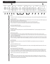
POWER OUTPUT SWITCH
This three position switch controls an attenuator which allows the maximum output of the amplifier to
be switched between 100%, 25% and 5% of rated power. Therefore, between 20 watts, 5 watts and 1
watt. This enables the user to drive the power stage hard, therefore producing the characteristic power
amp overdrive, but without such loud volumes being produced by the speaker.
On the lower settings it may be necessary to slightly increase the Resonance and Presence controls for
the desired tone. This is due to the change in damping factor when the speaker is driven less.
15
16
17
18
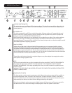
6505 MH
®
Rear Panel
1615 17
18 20
19 21 25 27
22 23 24 26 28