


FADE-IN PROTECTION
This feature operates every time the amplifier is turned on, or after a protect condition. During turn
on, the amplifier goes into protect mode and leaves the speaker load disconnected until the amplifier
determines that the operating status is normal. The Fade-In circuit attenuates the signal during the
initial turn on or protect operation. After relay release, channel gain gradually increases to the
attenuator setting to avoid unnecessary stress on the loudspeakers.
THERMAL PROTECTION
If the heatsink or power transformer reaches an abnormally high temperature, the amplifier will
protect itself by disconnecting the speaker load until the amplifier returns to a normal temperature.
During this time, the PROTECT LED will illuminate, and the cooling fan will operate at maximum
speed.
SHORT CIRCUIT
If an output is shorted, the LFC
™
, speaker relay and thermal circuits will automatically protect the
amplifier. The LFC circuit senses the short circuit as an abnormal load condition and reduces the
channel gain to a safe level for the load. In extreme or severe conditions, the speaker relays will
disconnect the load and initiate a power-on start-up sequence.
DC VOLTAGE PROTECTION
If an amplifier channel detects DC voltage or subsonic signals at its output terminals, the speaker
relay will immediately open to prevent loudspeaker damage. The PROTECT LED will illuminate as
notification of this condition.
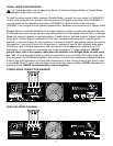
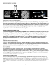
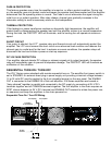
SEQUENTIAL TURN-ON / TURN-OFF
The ICA
™
Series comes standard with remote sequential turn-on. The amplifier front power switch is
set to STANDBY. An external direct plug-in power supply unit providing a nominal voltage between
12 to 24 volts DC must be applied to the 4-pin plugable terminal on the rear panel. The ENABLE
OUT is connected to the ENABLE IN of the next amplifier. ICA Series amplifiers are bussed or
“daisy chained” together in parallel and connected to the DC supply by connecting all 24 V DC+
terminals together and all COMMON terminals together. The first amplifier in the chain requires an
SPST closure between its 24 V DC+ terminal and ENABLE OUT terminal to initiate the power turn-
on sequence and keep the amplifiers in the chain powered on.
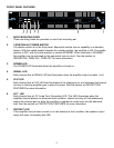
10
LEVEL B
-1
0
-6
-3
-10
-15
-30
-80
LEVEL A
-1
0
-6
-3
-10
-15
-30
-80
INPUT B
INPUT A
TM
A DIVISION OF PEAVEY ELECTRONICS CORP. MERIDIAN, MS MADE IN U.S.A.
MOUNT IN RACK ONLY
INSTALLER SUR SUPPORT DE MONTAGE SEULEMENT
24V DC+
ENABLE IN
COMMON
ENABLE OUT
OUTPUT POWER @ 4 OHMS IS 300 WATTS/CH
120 VAC
60 Hz
700 WATTS
RCHITECTURAL
COUSTICS
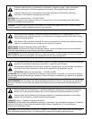
WARNING:
CAUTION
RISQUE DE CHOC ELECTRIQUE-NE PAS OUVRIR.
AVIS:
TO RAIN OR MOISTURE.
ELECTRIC SHOCK DO NOT EXPOSE THIS EQUIPMENT
TO REDUCE THE RISK OF FIRE OR
CLASS 2 WIRING
OUTPUT B OUTPUT A
(dB) (dB)
INDUSTRIAL CONTRACTOR AMPLIFIER
by
TM
600
Sequential Turn On/
Turn-Off Wiring
To 24 VDC+
of next amplifier
To
en
a
ble
In
of
next amplifier
To
common
of
next amplifier
24 VDC+
Common
Turn-on switch
Sequential Turn-On / Turn-Off Wiring