


INTRODUCTION
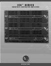
Congratulations on your purchase of an Architectural Acoustics ICA
™
(Industrial Contractor Amplifier)
from Peavey Electronics. Please read this manual carefully, especially the IMPORTANT SAFETY
INSTRUCTIONS on page 18. It contains information vital to safe operation of the power amplifier.
Also, please fill out and return the enclosed product registration card.
ICA Series amplifiers represent new levels of value and flexibility never before offered to the
contracting market. The ICA Series features models specifically designed to drive 4-ohm outputs,
70.7-volt outputs, and 100-volt outputs. 70.7 and 100-volt outputs can be driven directly, eliminating
the need for transformers or autoformers. These amplifiers cover almost every installed or
distributed sound power requirement imaginable.
ICA Series amplifiers are ruggedly built from high-quality components and feature comprehensive
protection circuits to protect your amplifier from those “real world” occurrences.
If you need setup or operational assistance for this product, please call the Peavey Electronics
Customer Service Department or your local Peavey Electronics representative. We appreciate
suggestions that may help us improve our products and/or service.
UNPACKING
Inspect the amplifier during unpacking. If you find any damage, notify your dealer immediately.
Only the consignee may institute a claim with the carrier for damage incurred during shipping. Be
sure to save the carton and all packing materials. Should you ever need to ship the unit back to
Peavey Electronics, one of its service centers, or the dealer; use only the original factory packing.
INSTALLATION AND MOUNTING
ICA Series amplifiers are 2 or 3-rack-space units of 15 3/4" (400 mm) depth that mount in a
standard 19" rack. On all amplifiers, front panel mounting holes are provided.
BASIC SETUP
1. Rack mount the amplifier in the location where it is to be used, remembering to allow for
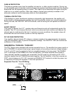
adequate access and cooling space. For more information, see the sections on
INSTALLATION AND MOUNTING and COOLING REQUIREMENTS.
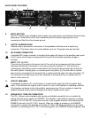
2. Make input connections to the plugable terminal blocks on the rear panel. Use the proper
connections for stereo, parallel, bridged mono, and grounding configuration. See the sections
on SIGNAL MODE CONFIGURATION and INPUT MODULE CONNECTIONS for more
information.
3. Connect speakers to the output barrier strip. Be sure to make the correct output connections
for stereo, parallel or bridged mono configuration. See the section on SPEAKER OUTPUT
CONNECTIONS for more information.
4. Make power connections, allowing for proper current draw. See the sections on IEC POWER
CONNECTOR and AC MAINS CIRCUIT SIZE REQUIREMENTS for more information.
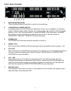
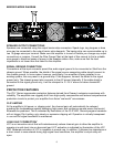
5. Turn the front panel 3-position AC POWER switch to ON and bring up the back panel LEVEL
(gain) attenuators to the desired levels.
4
ENGLISH