


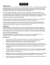
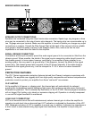
SIGNAL MODE CONFIGURATION
ICA
™
Series amplifiers are configured for Stereo (2-channel), Bridged Mode, or Parallel Mode
operation at the input connector.
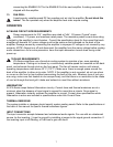
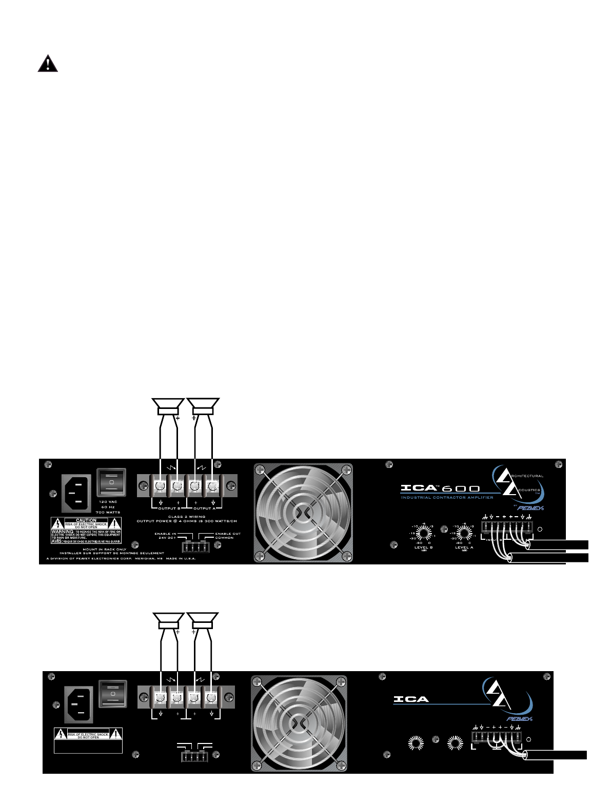
To send the same signal to both channels (Parallel Mode), connect the input signal to CHANNEL A
via the input connector. Run jumpers from the positive and negative terminals of the CHANNEL A
input connector to the respective terminals of CHANNEL B. Both channels then share the
CHANNEL A input signal but will operate independently. Speakers are connected as in Stereo Mode.
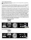
Bridged Mode converts the amplifier into a single-channel unit with a power rating equal to the sum
of both channel power ratings, and at a load rating twice that of the single-channel rating. In Bridged
Mode, the channels operate at opposite polarity of each other so that one channel “pushes” and the
other “pulls” equally. Signal is connected to the input connector with one jumper connecting the
positive (+) terminal of Input A to the negative (-) terminal of Input B, and another jumper connecting
the negative (-) terminal of Input A to the positive (+) terminal of Input B. Both channel attenuators
(A & B) are used to control signal level, and both must be at the same level, preferably at 0 dB
attenuation. The speakers are connected only to the designated “+” output terminals. NEVER
ground either side of the speaker cable when the amplifier is in Bridged Mode as both sides
are “hot”. If an output patch panel is used, all connections must be isolated from each other and
from the panel. For ICA Series amplifiers, the minimum nominal load impedance in Bridged Mode is
8 ohms; this is the equivalent of driving both channels at 4 ohms. Driving loads of less than 8 ohms
may activate the LFC circuit and may also cause a thermal protect condition. NOTE: Regardless of
operating mode, NEVER connect amplifier outputs together!
STEREO MODE CONNECTION DIAGRAM
PARALLEL MODE DIAGRAM
8
LEVEL B
-1
0
-6
-3
-10
-15
-30
-80
LEVEL A
-1
0
-6
-3
-10
-15
-30
-80
INPUT B
INPUT A
TM
A DIVISION OF PEAVEY ELECTRONICS CORP. MERIDIAN, MS MADE IN U.S.A.
MOUNT IN RACK ONLY
INSTALLER SUR SUPPORT DE MONTAGE SEULEMENT
24V DC+
ENABLE IN
COMMON
ENABLE OUT
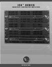
OUTPUT POWER @ 4 OHMS IS 300 WATTS/CH
120 VAC
60 Hz
700 WATTS
RCHITECTURAL
COUSTICS
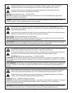
WARNING:
CAUTION
RISQUE DE CHOC ELECTRIQUE-NE PAS OUVRIR.
AVIS:
TO RAIN OR MOISTURE.
ELECTRIC SHOCK DO NOT EXPOSE THIS EQUIPMENT
TO REDUCE THE RISK OF FIRE OR
CLASS 2 WIRING
OUTPUT B OUTPUT A
(dB) (dB)
INDUSTRIAL CONTRACTOR AMPLIFIER
by
TM
600