


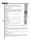
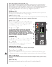
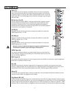
Green Signal LED and Red Clip LED (17)
The green Signal LED and red Clip LED are used to set the operating input level to the PV
®
10 and PV
®
14
effects processors. The signal level to the processor is affected by channel fader, the effects send and the
effects send master controls. Start with the master control set to 0 (12 o'clock) and adjust the channel sends so
that the signal LED lights and the clip LED blinks on occasionally, if at all. The clip LED lights 6 db below
clipping. Pressing the EFX defeat mutes the effects signal and lights the clip/mute LED.
EFX Return (18)
Once the input level is set (see 17) use the EFX return control to mix the effects processor output into the
main left/right outputs. Remember, a little reverb goes a long way.
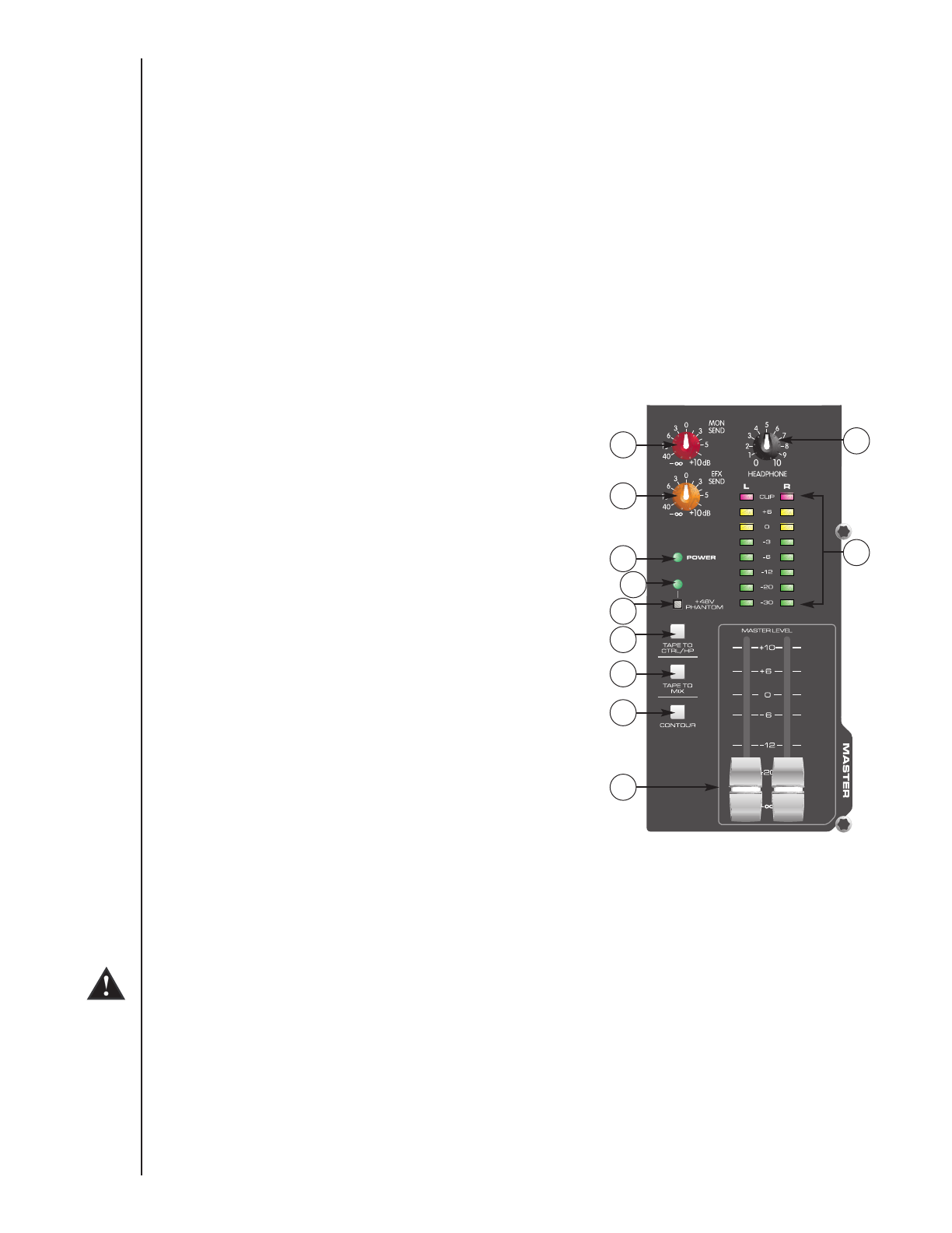
MON Send Master (19)
This is the master output level control for the monitor mix. The output level sent to the Monitor Send jack (36)
is controlled by the channel monitor send controls (6) and by this master control.
EFX Send Master (20)
This is the master output level control for the EFX mix. The output
level sent to the EFX Send jack and the internal effects processor is
controlled by the channel level controls (12), the channel EFX send
controls (7) and by this master control. The 0 position is the
recommended setting for this control.
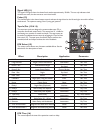
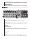
Headphone Level (21)
This knob sets the headphone and control room output levels. To
avoid damage to your hearing‚ make sure to turn the dial fully
counterclockwise before using headphones. Slowly turn the knob
clockwise until you reach a comfortable listening level. Normally, the
signal in the headphones is the left/right signal. If the Tape to Control
Room (26) is engaged‚ the tape signal is also included.
LED Meters (22)
Two eight-segment LED arrays are provided to monitor the levels of
the main left/right outputs. These meters range from -30 dB to +19
dB. 0 dB on the meter corresponds to +4 dBu at the outputs.
Power LED (23)
This LED indicates AC power is supplied to the unit‚ the power
switch is on and the unit is functioning properly.
Phantom Power LED (24)
This LED lights when the Phantom Power Switch (25) has been engaged.
Phantom Power Switch (25)
Applies +48 VDC voltage to the input XLR connectors to power microphones requiring phantom power.
If phantom power is used, do not connect unbalanced dynamic microphones or other devices to the XLR inputs.
Tape To CTRL/HP (26)
Depressing this switch adds the tape return to the Control Room (38) and Headphone Outputs (40) for zero latency
monitoring.
Tape to Mix (27)
Depressing this switch routes the signal from the Tape Inputs (13) to the Main Outputs (39).
10
19
20
21
22
23
25
24
26
27
28
29